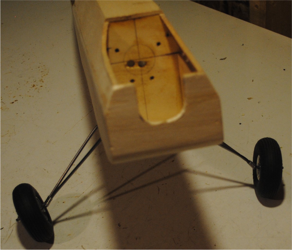
For general info on building wire struts, check out the Building Wire Cabane Struts article first.
I think it’s a good idea to make the solder joints in your landing gear while the struts are attached to the fuselage, because the fuselage provides a good anchor for holding everything straight. I think it’s also a good idea to make the final bends in the wires as the landing gear is being assembled, rather than prebending everything. Here’s a photo of the two wires attached to the fuselage. Notice that each wire is bent in only two places. These initial bends were made with a K&S wire bender. If you are going to make struts for multiple airplanes, I strongly recommend getting this tool.
The axle will be made by bending the end of the longer strut. Don’t worry about that now. You can see the black mark where the axle will be bent. Use this mark as a guide for bracing strut placement.
The last half inch of the bracing strut will be bent to match the angle of the axle strut. First, observe which way you need to bend the brace.
Then, while keeping the wire in approximately the same position, bend the end of it to the correct angle.
My favorite tool for bending landing gear wire (other than the K&S bender clamped in a vise) is a pair of crescent wrenches. It takes some practice, but it works. For this project I am bending 1/8″ wire, which takes a bit of effort but is actually pretty easy. 3/32″ wire is a piece of cake. 5/32″ wire is challenging, but I can still do it with big wrenches. Anything bigger than that, and I suggest putting it in the K&S bender. You can still do this with the wire attached to the plane, because as the wire gets bigger, the struts also get longer, so you should have adequate clearance. If you don’t have enough clearance, place a mark on the wire on the side in the direction that the end will be bent. Then you can take it off the plane and be fairly certain that you will bend it the right direction.
Now that the end of the brace is bent to the correct angle, the wires are cleaned with acetone, the mark is replaced with a Sharpie marker, and the joint is wrapped with copper wire.
If you move on to the second joint without soldering the first, the first one will get all out of whack, so it’s a good idea to solder the first joint before doing anything else.
Next the other side is bent, cleaned, and wrapped.
After soldering, this is what the landing gear looks like when the model is upright.
The axle needs to be bent into place. The reason why I save this step for last is because it’s kind of hard to get the axle in exactly the right orientation before you see where the landing gear is going to end up. Now that everything is in place on the plane, it’s a lot easier to just stick a wrench on it and bend it into place. It needs to have a bit of toe-in, and a bit of camber.

Now the wheels are added.
To my eye, the camber looks like a bit much, so I’ll probably be adjusting the axles a bit. The more you bend them and re-bend them, the more they bend by themselves when you land, so try to get it right on the first few tries.
As you can see, this is a cheap, quick, easy project. I didn’t go out of my way to make it perfect. It’s just for demonstration purposes (actually I’ll be using it on this plane even though it’s not perfect). If you are a perfectionist, you can bend your struts a lot prettier than the ones in my photos. I did a landing gear for a Big John biplane that were really beautiful. The struts were straight, the bends were crisp, and it even included bungee cords (rubber bands) for suspension. I think it’s a lot more fun than just slapping a factory made aluminum landing gear on the plane.


