
Aileron controls have gone through several distinct historical phases. In the 1960s and 70s most plans showed ailerons controlled by a single servo at the wing root via push rods and bell cranks. Then it became popular to drive the ailerons from a single center servo via torque rods. This is seen a lot on kits and plans from the late 70s through the early 2000s. Nowadays it seems everybody wants to mount the servos outboard in the wing panels and drive each aileron with its own servo. This method has some advantages. It allows the use of electronic mixing to turn the ailerons into flaperons or spoilerons. Also, it’s a no-brainer to run a push rod directly from a servo to an aileron. But the humble torque rod is not dead. I still use them on most of my planes because I like the clean installation. I don’t have to run wires into the wing panels, and I don’t have servos hanging out in the wind. Also, for those who like electronic mixing, each aileron can still have its own servo. Just put them in the middle, one per torque rod.
If you wish to install torque rods in your plane, make sure your hardware is up to the job. I typically bend my torque rods from 4-40 threaded mild steel push rods for planes up to 60 size. Bigger and more demanding planes require music wire and possibly other considerations. If I don’t have the correct hardware on hand when building a bigger plane, I usually opt for servos mounted in the wings. But I really like torque rods so I usually do what it takes to use them.
The first thing to do is figure out what sort of wood block you’re going to put over your torque rods. Look at a few trainer plans on outerzone and you’ll get some ideas. Some planes have hard wood torque rod blocks to prevent damage from the rubber bands used to hold the wings on. Some planes have a block made from trailing edge stock, then reinforced with thin plywood. I like using square sticks or rectangular blocks rather than trailing edge stock because even if the wing trailing edge is slanted I can still mount the blocks and simply sand away whatever is not needed.
First put the wing in place to make sure it fits correctly. Any gaps or unevenness should be corrected now.

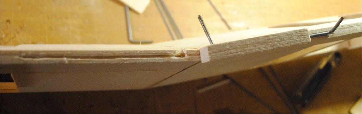
My wing looks good, so now I need to measure the gap to see how big of a piece of balsa is needed to fill the space.


Looks like a 3/8 x 3/8 stick should do the job. The blocks need to protrude far enough away from the fuselage to avoid interference, especially in the case of a wing to be retained by rubber bands. As you can imagine, if there were only a half inch of space between the aileron and the fuselage, the ailerons would have a greater chance of accidentally encountering either the rubber band or the dowel itself. On my plane the wing will be attached with bolts, so no matter, but I still like to get a little bit of distance between the aileron and the fuselage.

When I took the photos I assumed that you know how a torque rod is put together and how it works. But now that I’m thinking about it, here’s a short description. It’s basically a 4-40 mild steel rod with a 1/8″ ID nylon or brass tube on it to act as a bearing. You can find these in kits at the hobby store, or you can make them yourself. Put a bend in the threaded end, being careful to stay away from the threads themselves. If you bend the rod at the threads or at the end of the threads, it will most likely break. Then put the bearing on, trimmed long enough to reach the end of your balsa block, then bend the end that goes into the aileron. Put a drop of light oil into each end of each bearing tube to keep glue out of there. Getting glue into the tube really sucks, and you’ll have to start over.
After you have the torque rod assembled, put it in the correct location in relation to your block and press it to make an impression in the wood. Note: The “correct position” also implies that the arms will be close enough together in the middle to keep them from hitting wing mounting blocks and other push rods in the fuselage.

Also make marks where you will have to cut the clearance hole for the control arm. Here’s what it looks like after it’s marked.

Have you ever wondered about the round grinding tool that comes with a Dremel set? Now it’s time to use it. Get the one that has the same diameter as your bearing tube, and grind a trough that will accommodate the tube to exactly half of its thickness.
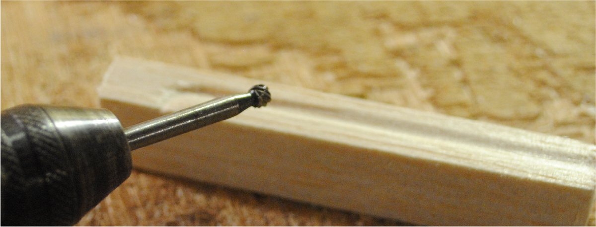
Check for correct depth.


When you are certain that the slot is cut correctly, glue the bearing tubes into place. Use just enough medium CA to hold them. Don’t put a trainload of glue in there or it will squeeze out all over the place and interfere with proper fitment when you try to put the blocks on the wing.

Now that the torque rods are attached to the blocks, use them to mark the wing trailing edge the same way you marked the blocks earlier.

Cut the slots in the wing trailing edge. This time you’ll have to cut an extended slot to accommodate the rod that attaches to the aileron.

Check to be sure that the slot is deep enough by trying to rock the block up and down. If it rocks, that means that the tube is bottoming out in the slot, and the slot should be cut deeper. When it is deep enough the gap will close on both sides and the wood can be glued together with medium CA. Thin CA can be used, but care must be taken to prevent it from running and gluing the rods in place.

Note that these blocks are big and square, and they do not follow the contour of the wing surface. This is OK. In fact it’s preferable because if you use a piece of trailing edge stock you will have to try harder to make sure it’s attached at the correct angle. With blocks you just stick them on and don’t worry about it. Here’s what it looks like with both blocks in place and ready for sanding.

And here’s what it looks like after sanding.
