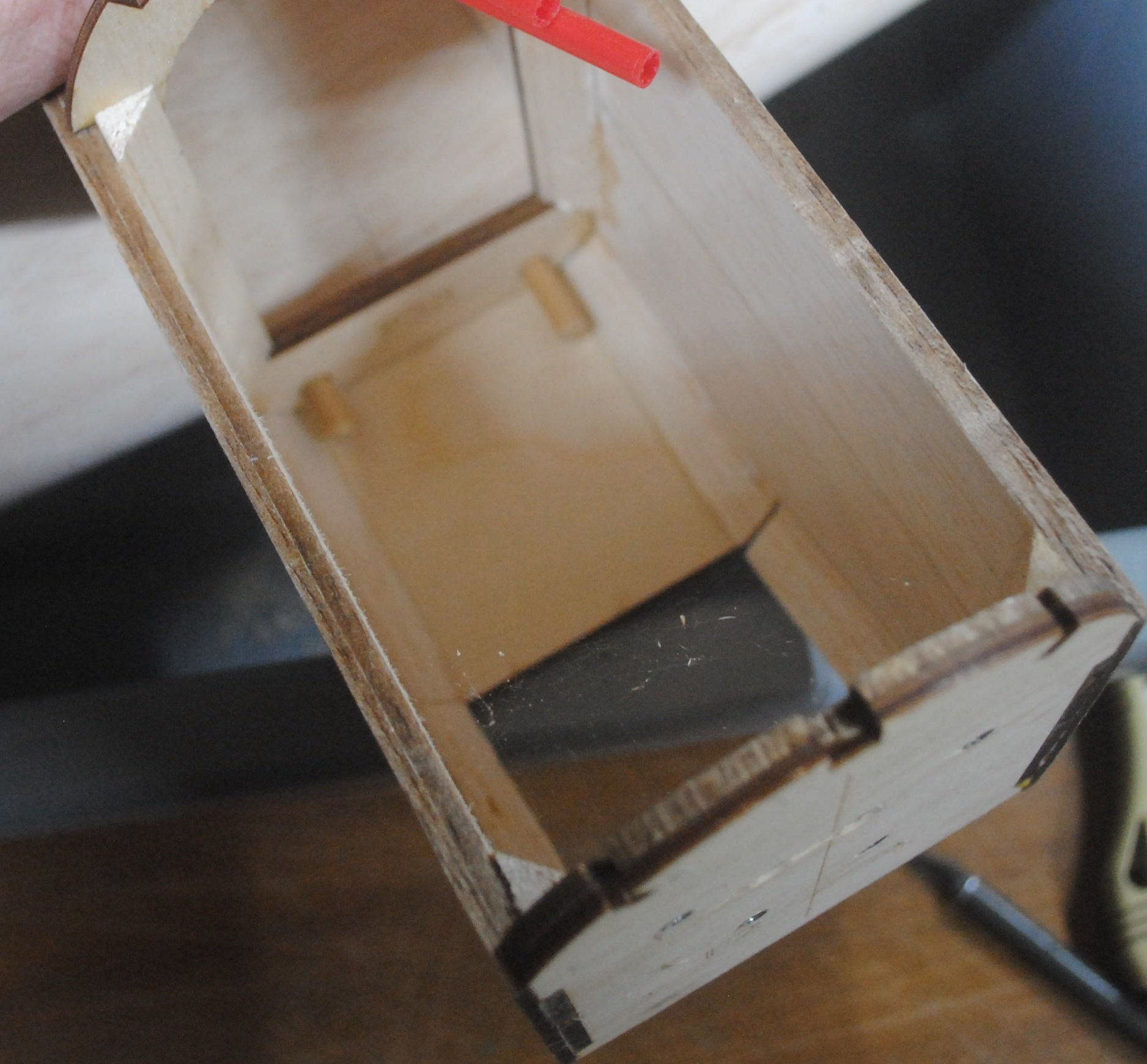
There are just a few more things to do before joining the wings at the root. W1 is a little piece of plywood that is intended to make it less likely that your wing dowel will rip out of the balsa leading edge. It attaches to the back of the leading edge stick, on the inside of the wing. You have to reach in there from the back, in between the spars.
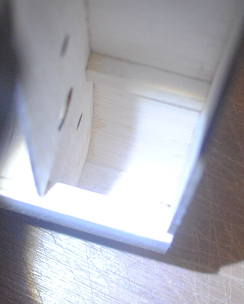
You can poke W1 with your hobby knife, apply the glue, and stick it in there to reach the back of the leading edge.
Once it’s in place you can also drop glue around the edges of W1 just to make sure.
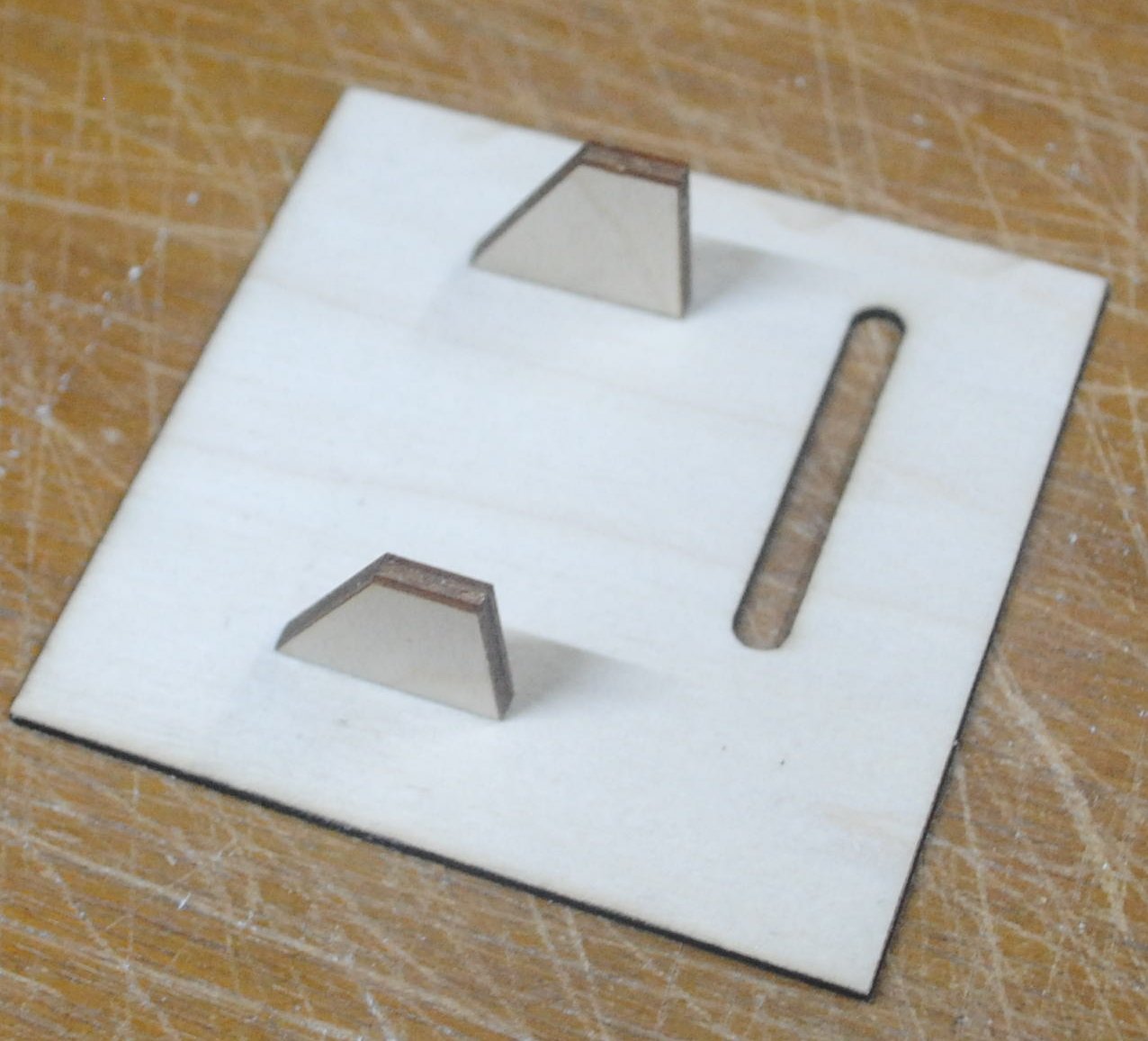
The kit includes parts for two different aileron servo mounting methods. You can mount the servo on the inside of the servo plate so just the servo arm sticks out through the slot, or you can use the other plate and mount the servo in the hole so the whole top of the servo is outside the wing.
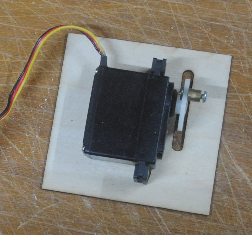
Starting with the first method, the first thing to do is glue the screw blocks to the back of the servo plate. Find the spot where the servo goes, with the output arm centered over the slot. Obviously your servo will have an arm, not a wheel, but my servo has a wheel because it’s convenient for lining up the servo.
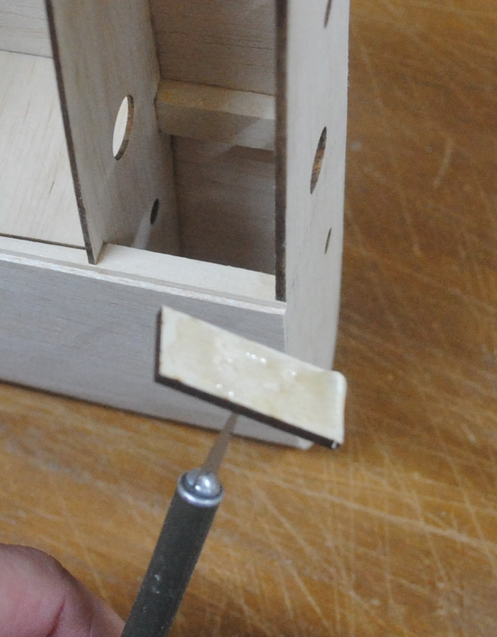
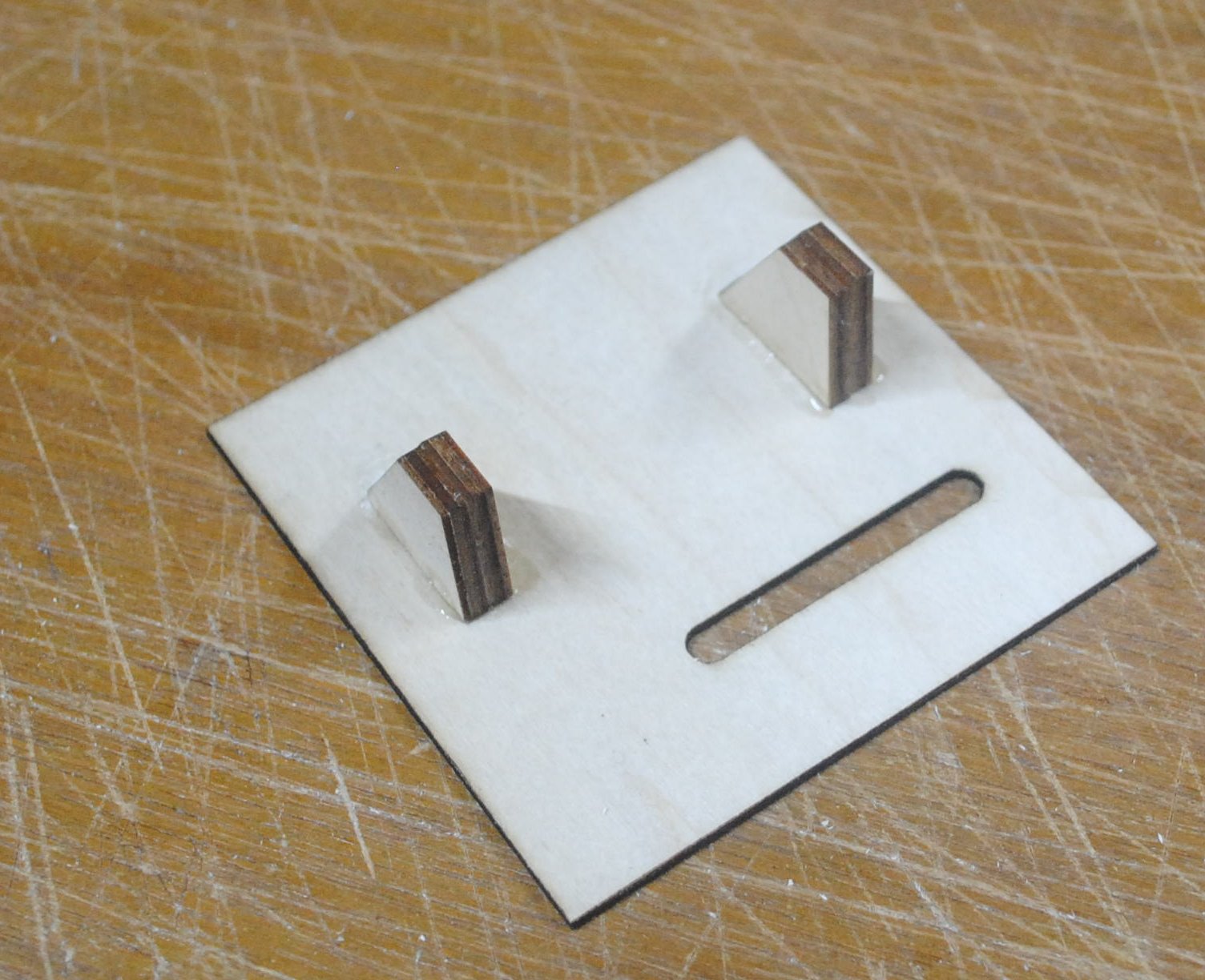
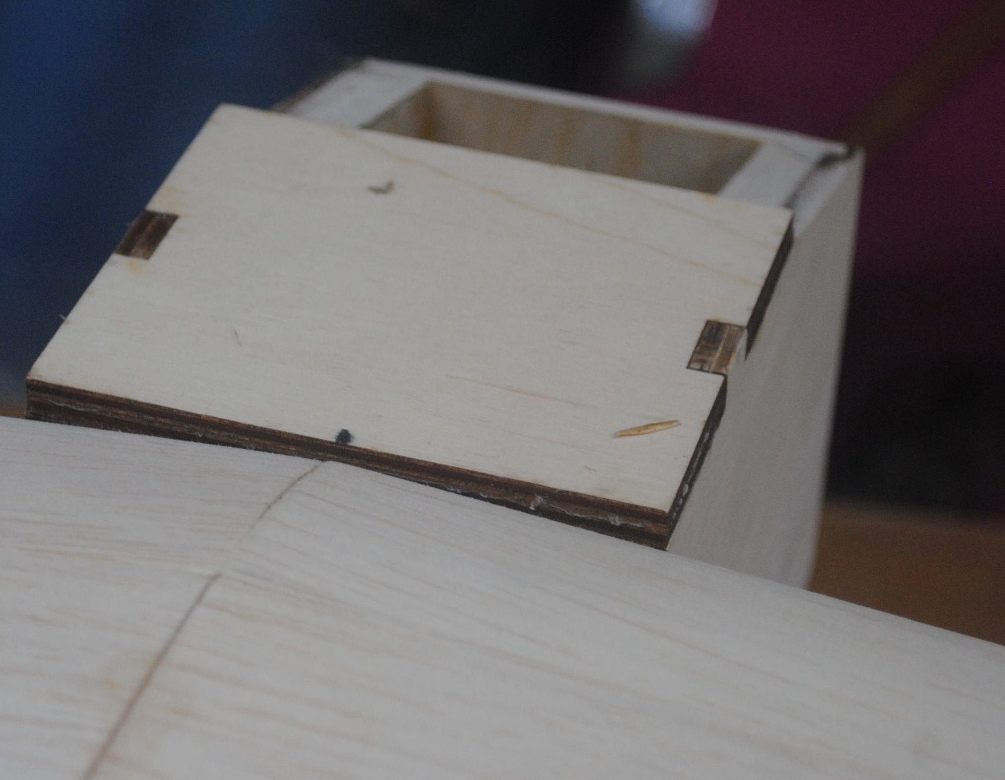
The screw blocks are two layers of 1/8″ birch plywood. Put glue on one edge of one piece of plywood and stick it to the servo plate, using the servo as a guide. Then repeat with one layer on the opposite side.
Apply more glue, and apply glue to the face of another piece, and stick the second layer to the first layer. Repeat for the opposite side. As you can see in the following photo I have reinforced the joint with more medium CA around the assembled screw blocks.
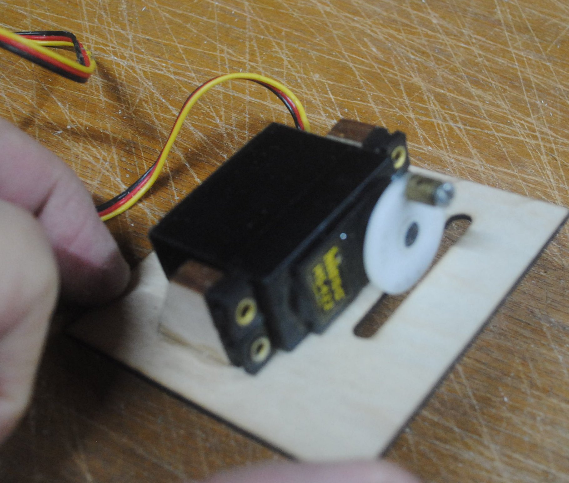
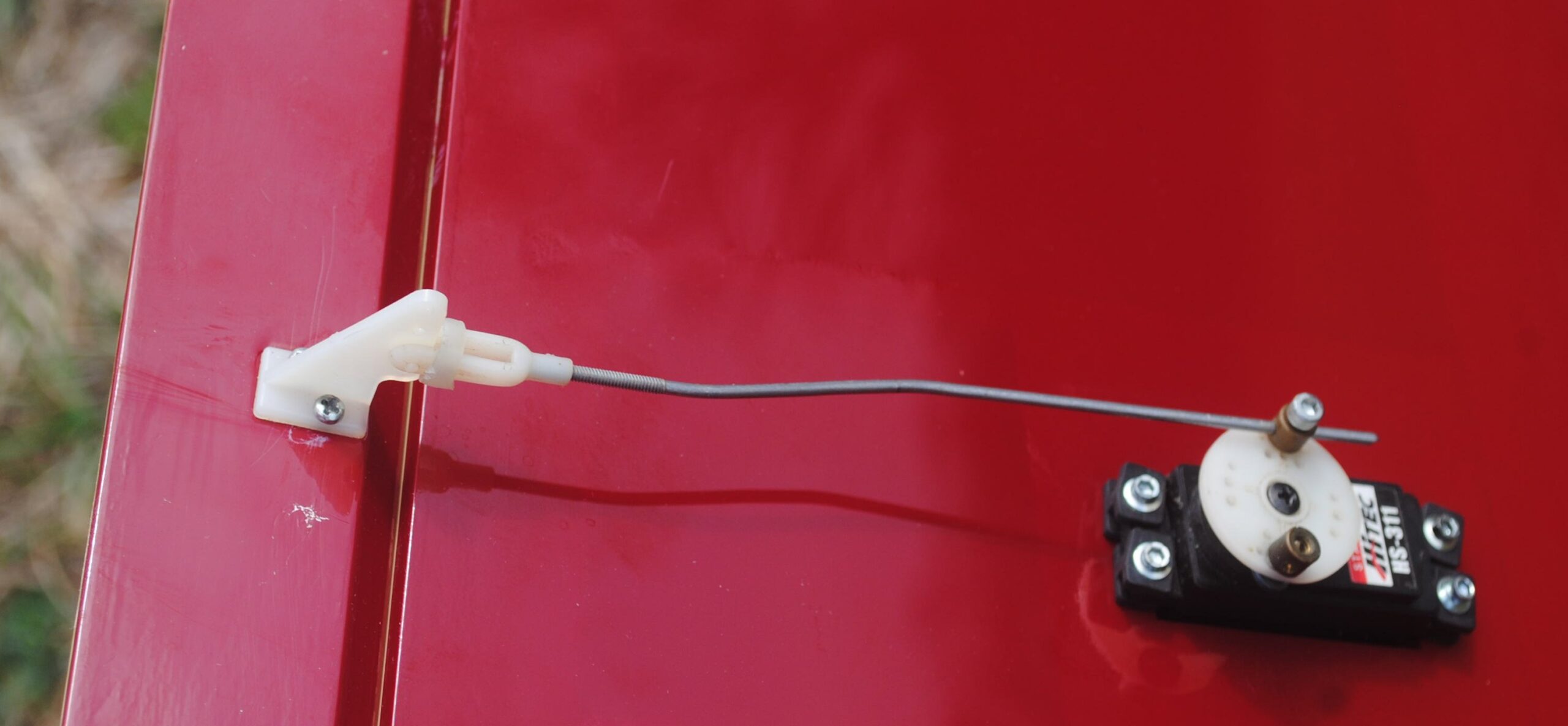
Here’s how it looks with the servo in place.
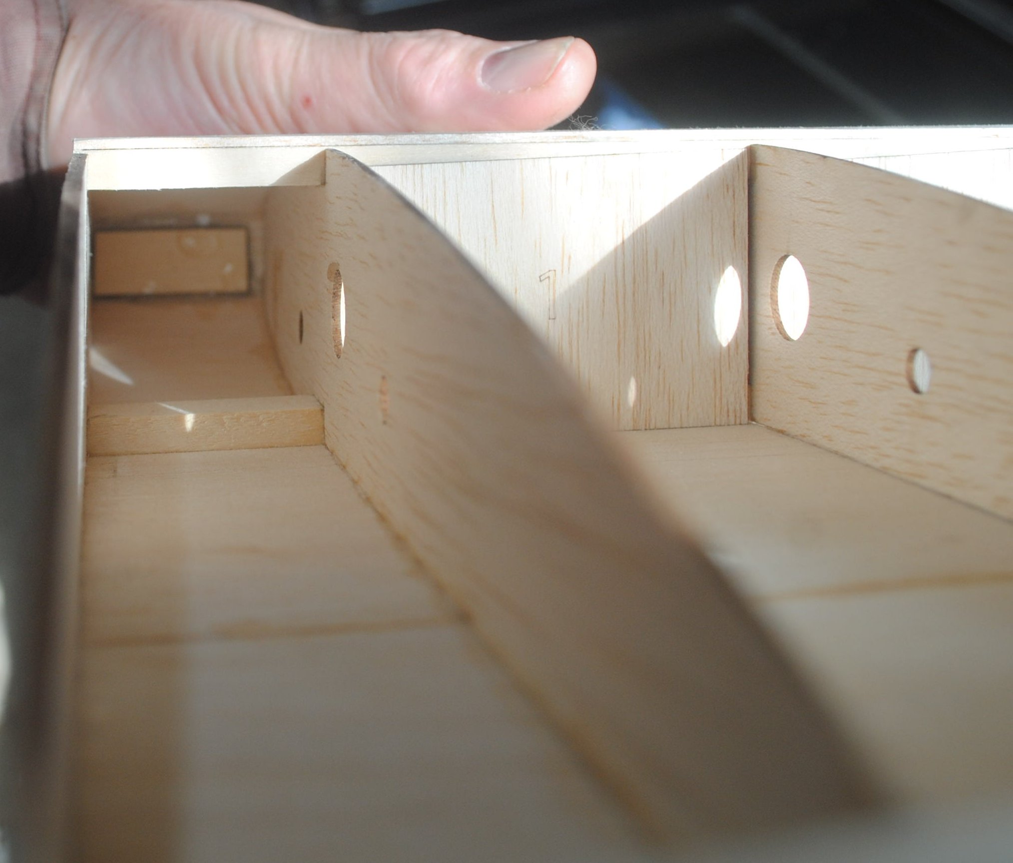
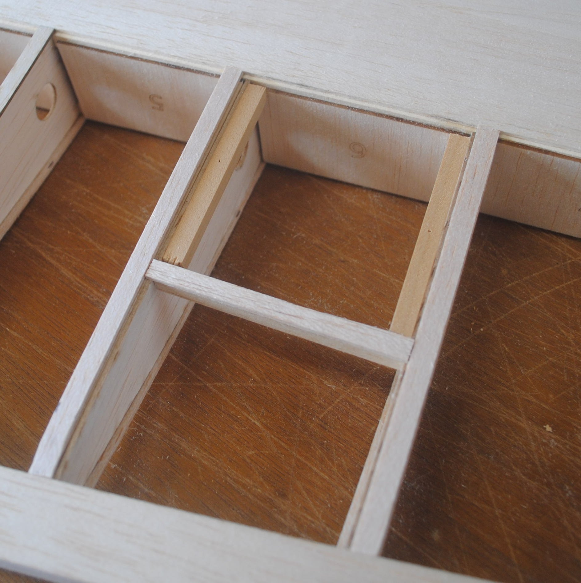
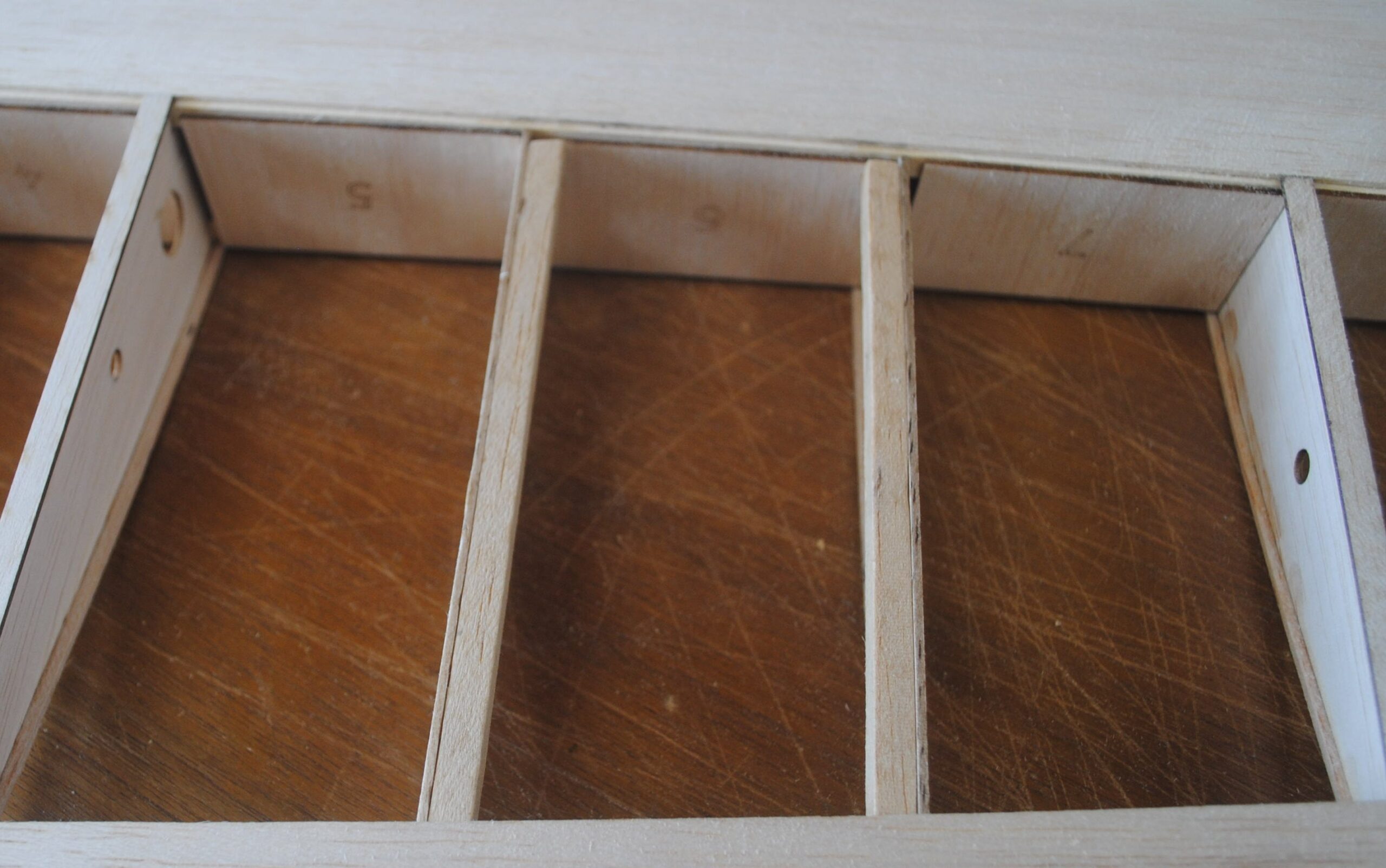
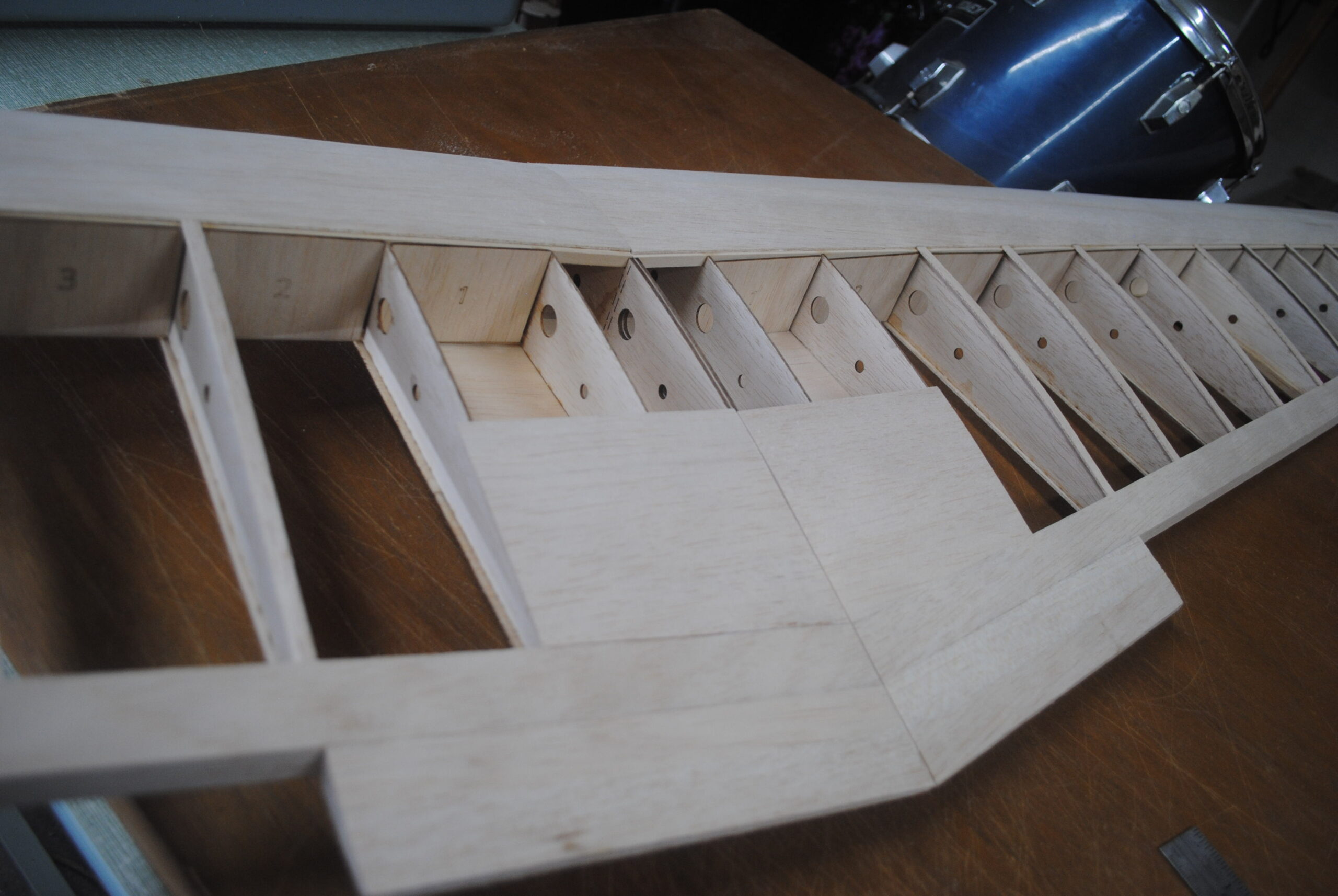
Attach 1/4 x 1/4 balsa sticks to the ribs on either side of the servo bay. The sticks should be on the outside of the servo bay. Also place a balsa stick at the rear of the servo compartment between the two ribs. Place it so the aft edge of the servo plate will land halfway across the stick.
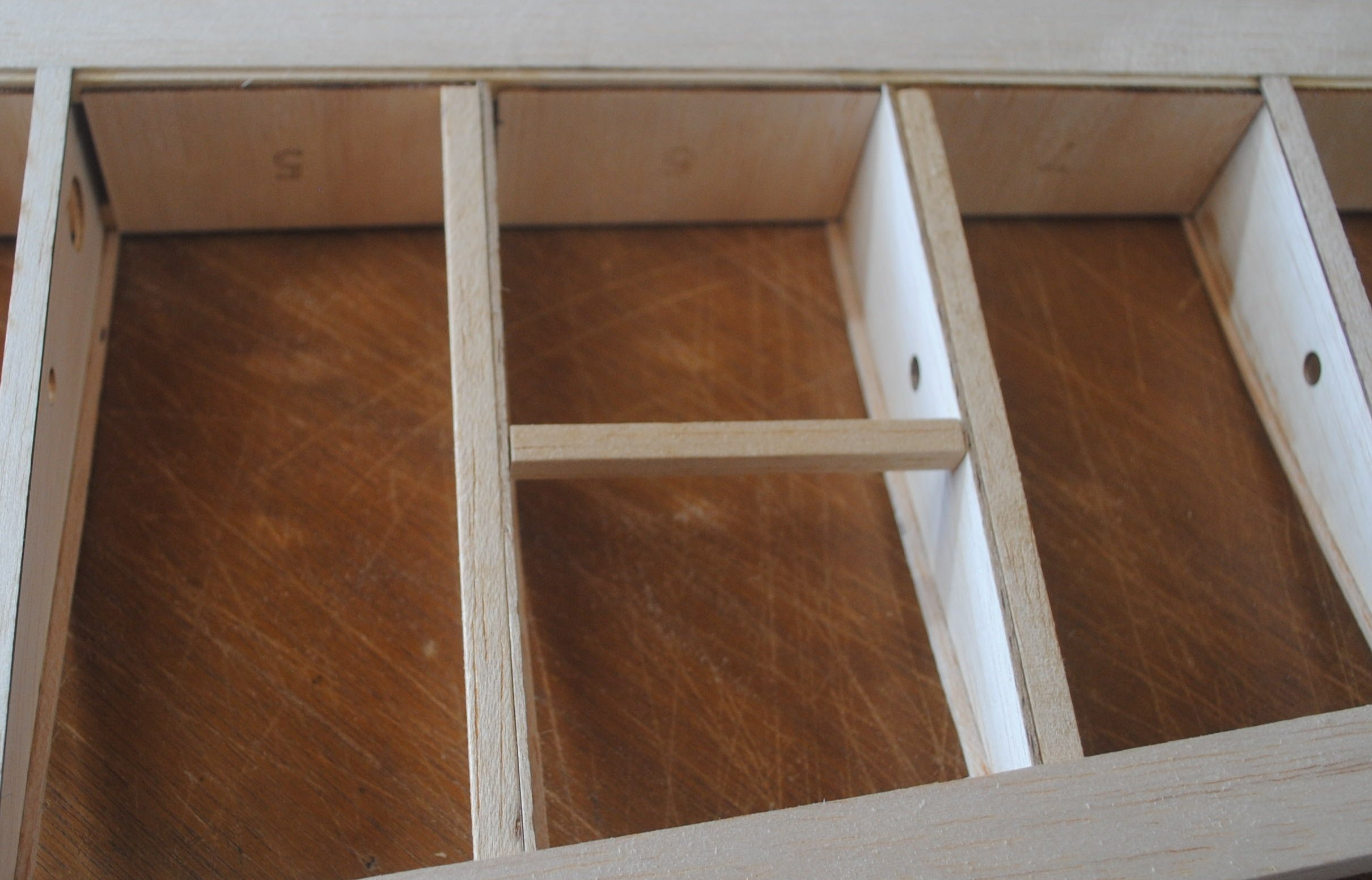
Attach 1/4 x 1/4 bass wood sticks to the two ribs, this time on the inside the servo bay. Place 1/16″ balsa cap strips to outline the servo plate and bring everything flush with the wing sheeting. Try to leave just a tiny bit of space around the servo plate to accommodate the covering film.
Mark the screw locations on the servo plate.
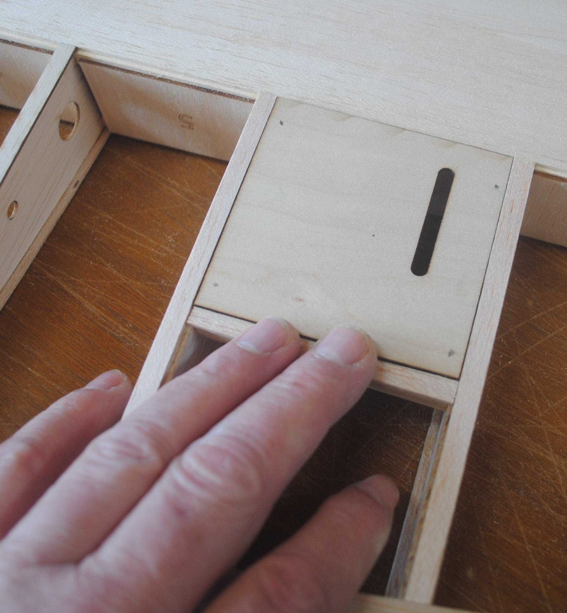
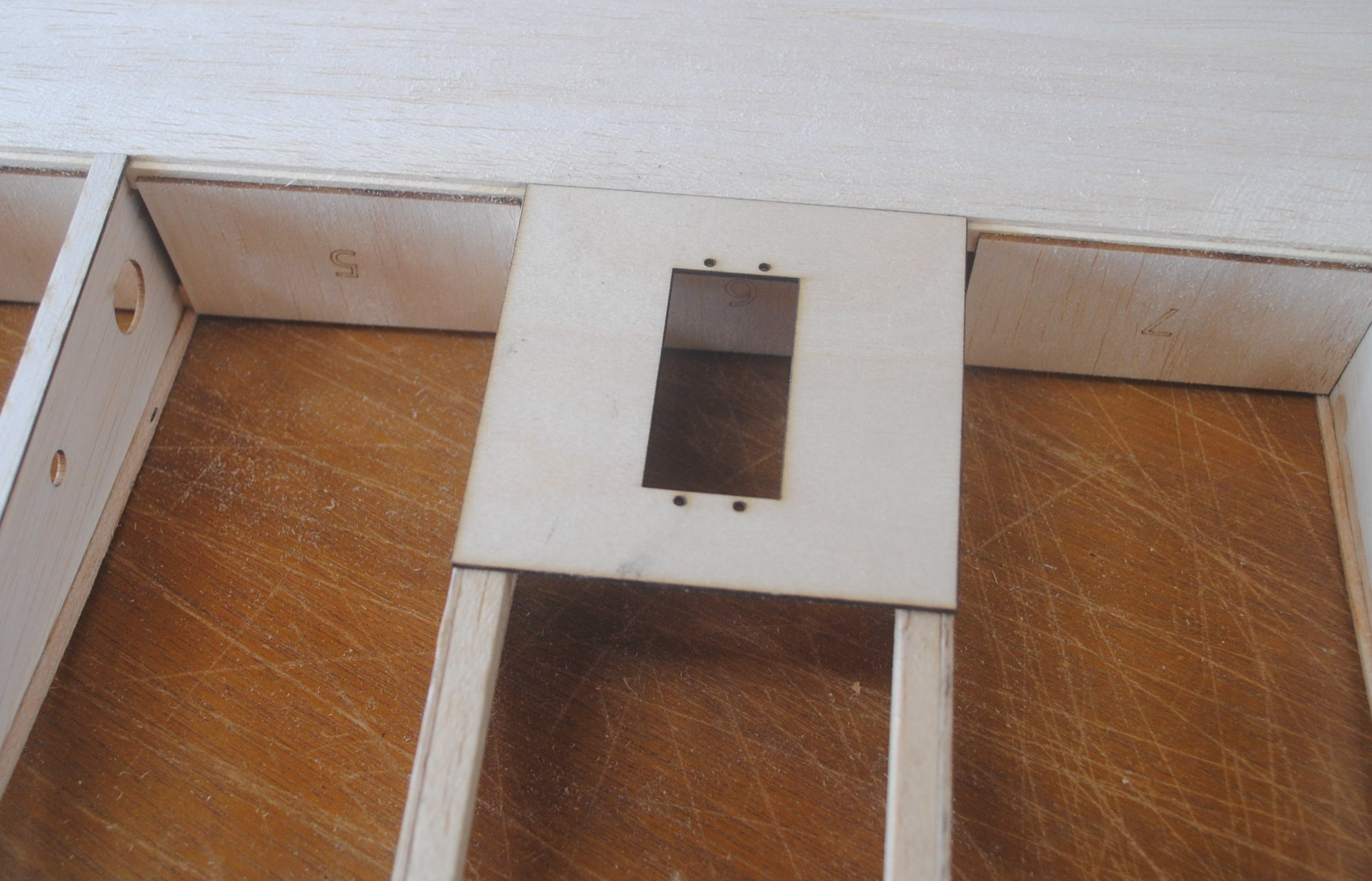
If you prefer to mount the servo with the entire top part outside the wing, use the other servo plate. Here’s what it will look like when finished.
First attach the 1/16″ birch ply screw backup plates on the inside of the servo plate.
Attach the 1/4 x 1/4 balsa sticks to the ribs in the servo bay. In this case the sticks are inside the servo bay.
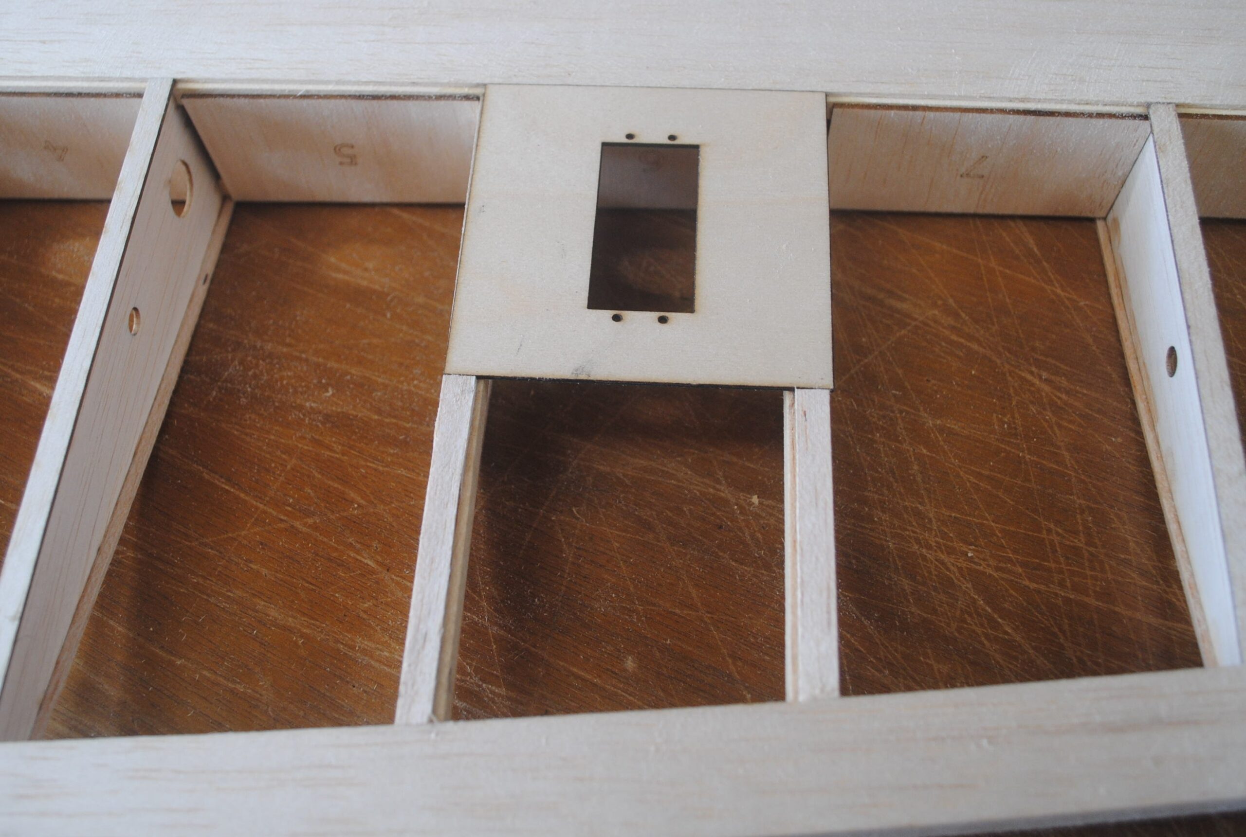
Glue the servo plate to the wing.
Attach cap strips aft of the servo plate.
If you want to attach this servo plate with screws, build the support structure as described for the other type, and then you’ll have your choice of which type of installation you want. You could even switch later if you want to.
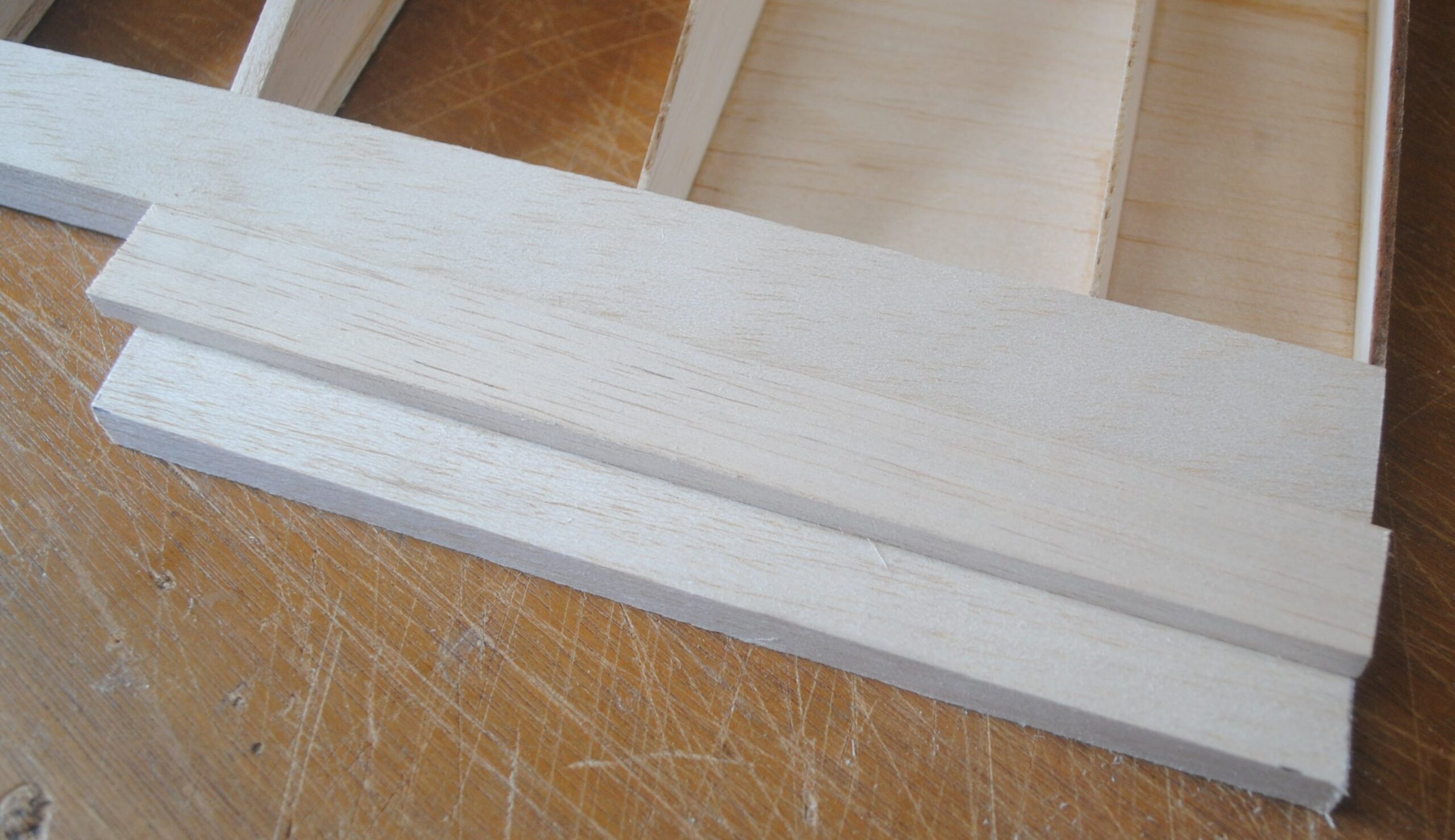
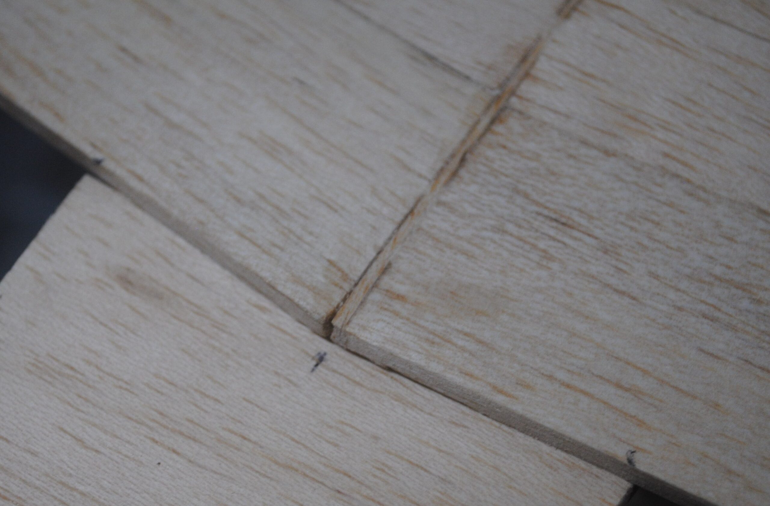
The wing center section has trailing edge blocks that are made in two layers. The first layer is 3/8 x 1 ½. It should extend to rib #4, or somewhere in that neighborhood. The exact length isn’t critical so don’t sweat it.
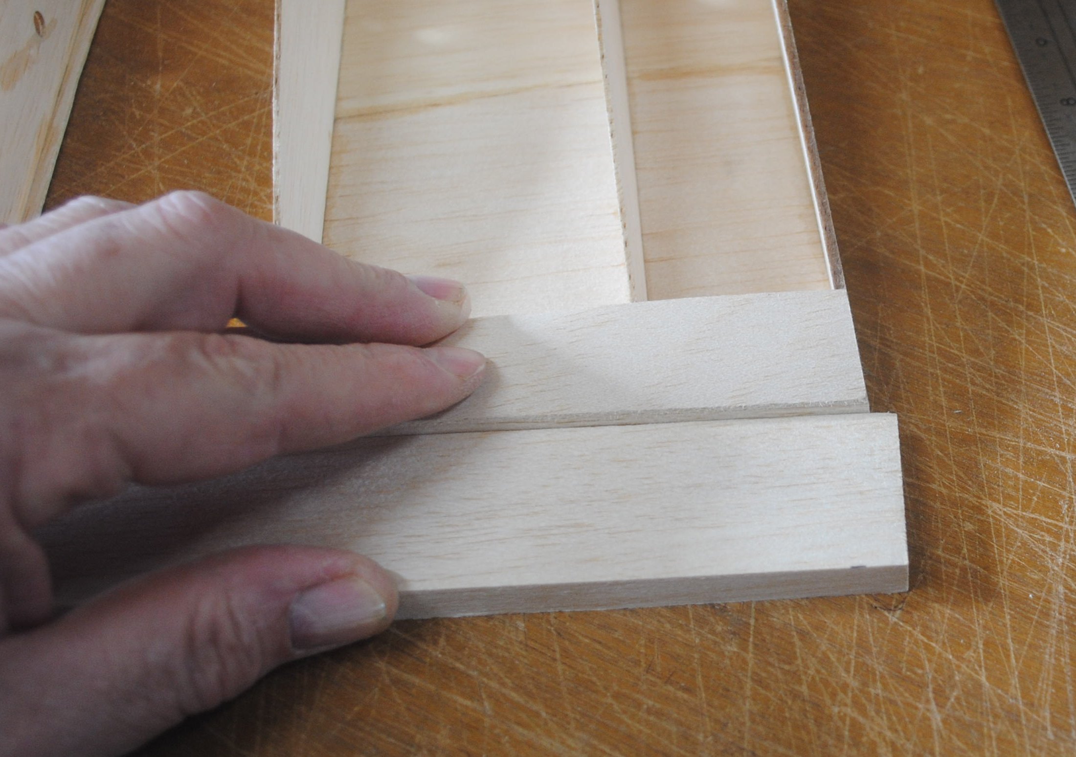
Use a ruler and pen to mark the balsa at an angle to match the root rib.
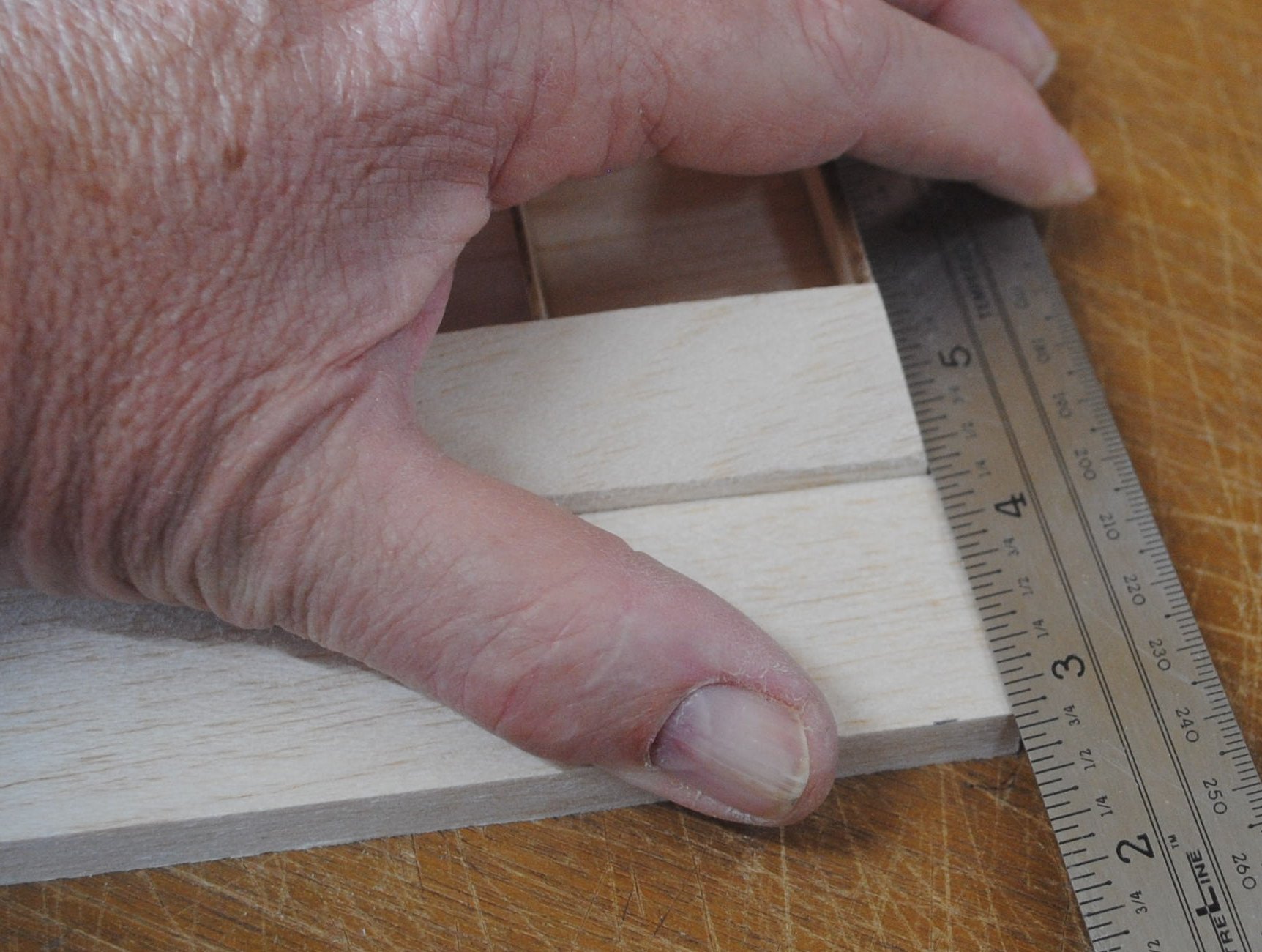
Turn the piece around and make the same mark on the other end.
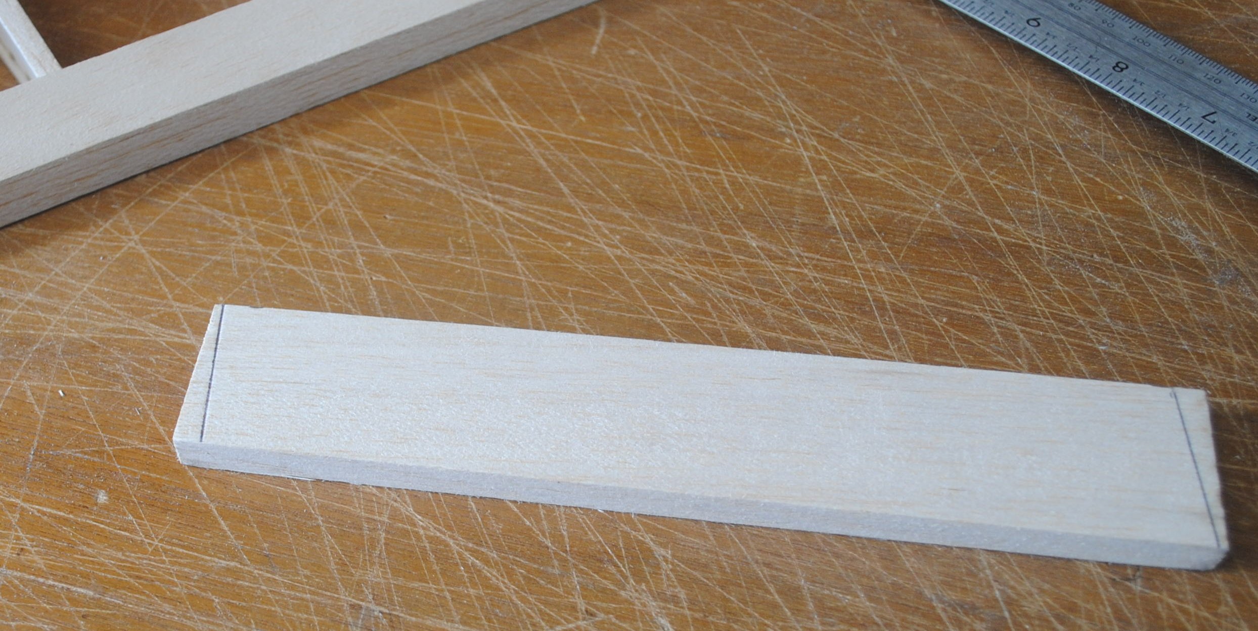
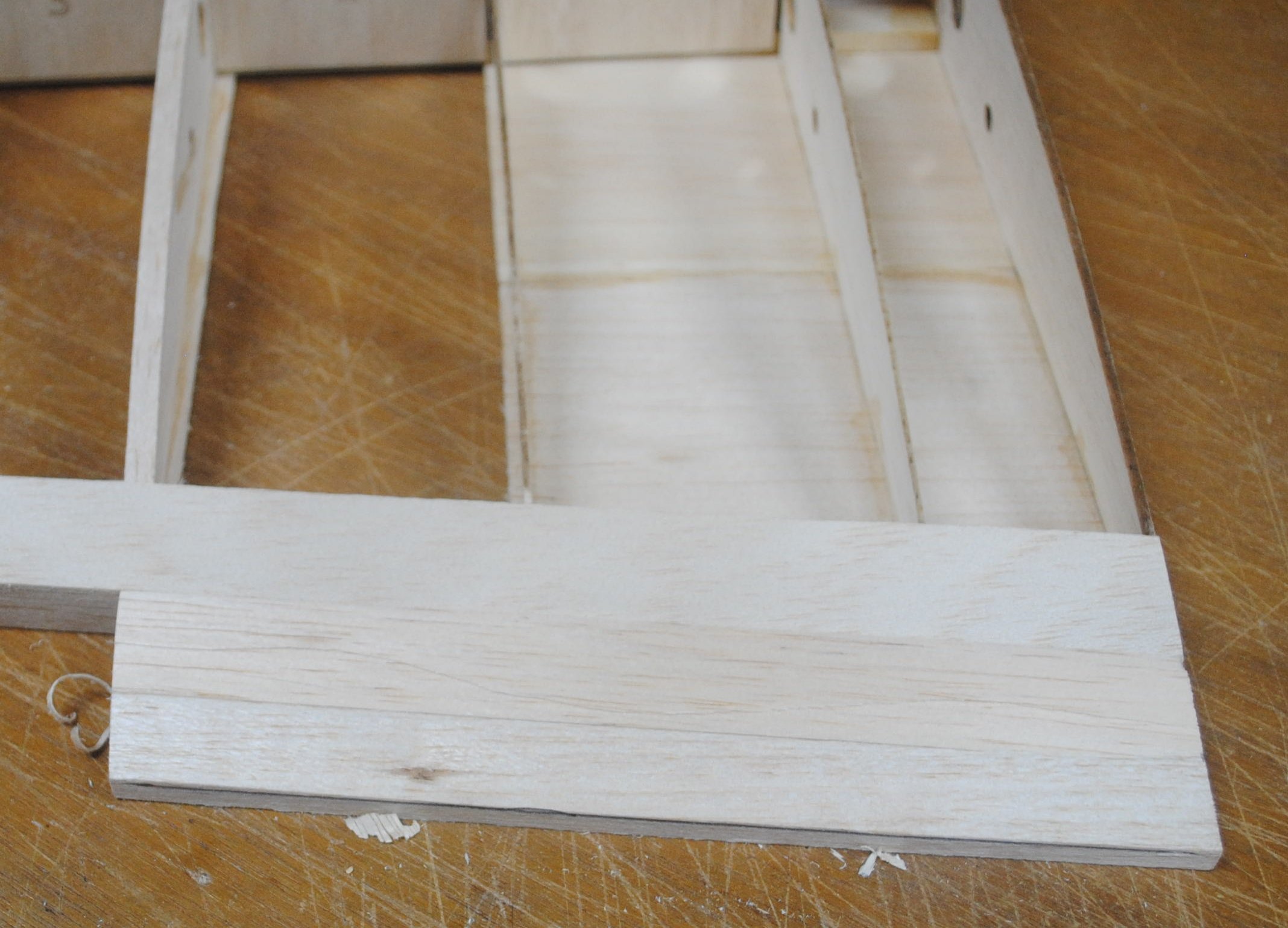
The second layer is 1/4 x 3/4.
The block’s finished dimensions are 9/16″ tall in front and 3/16″ tall at the trailing edge. Sand the ends flush and carve the piece down to rough dimensions, then attach it to the wing.
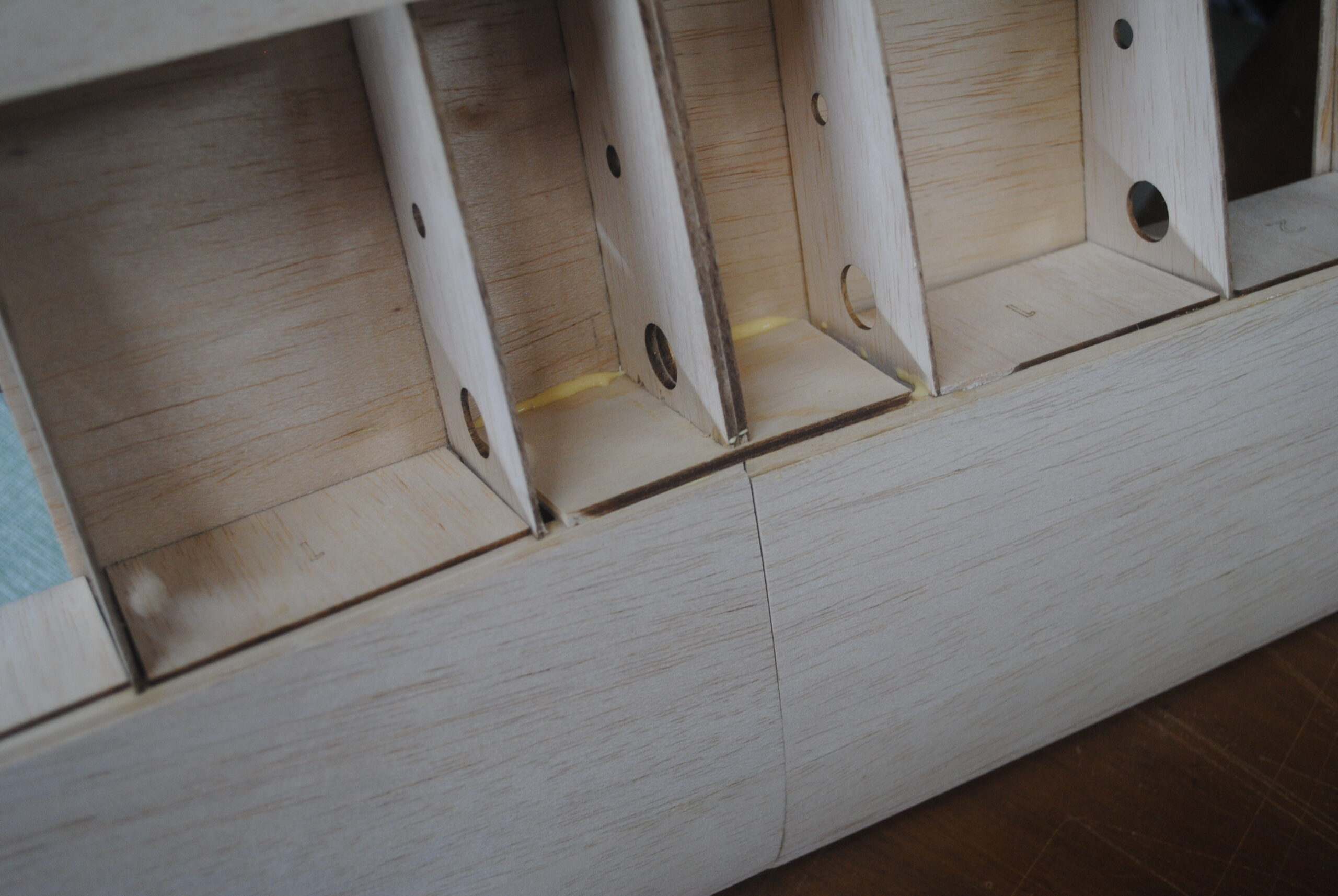
Cut sheeting to fit the top of the wing at the center section but don’t attach it with glue yet.
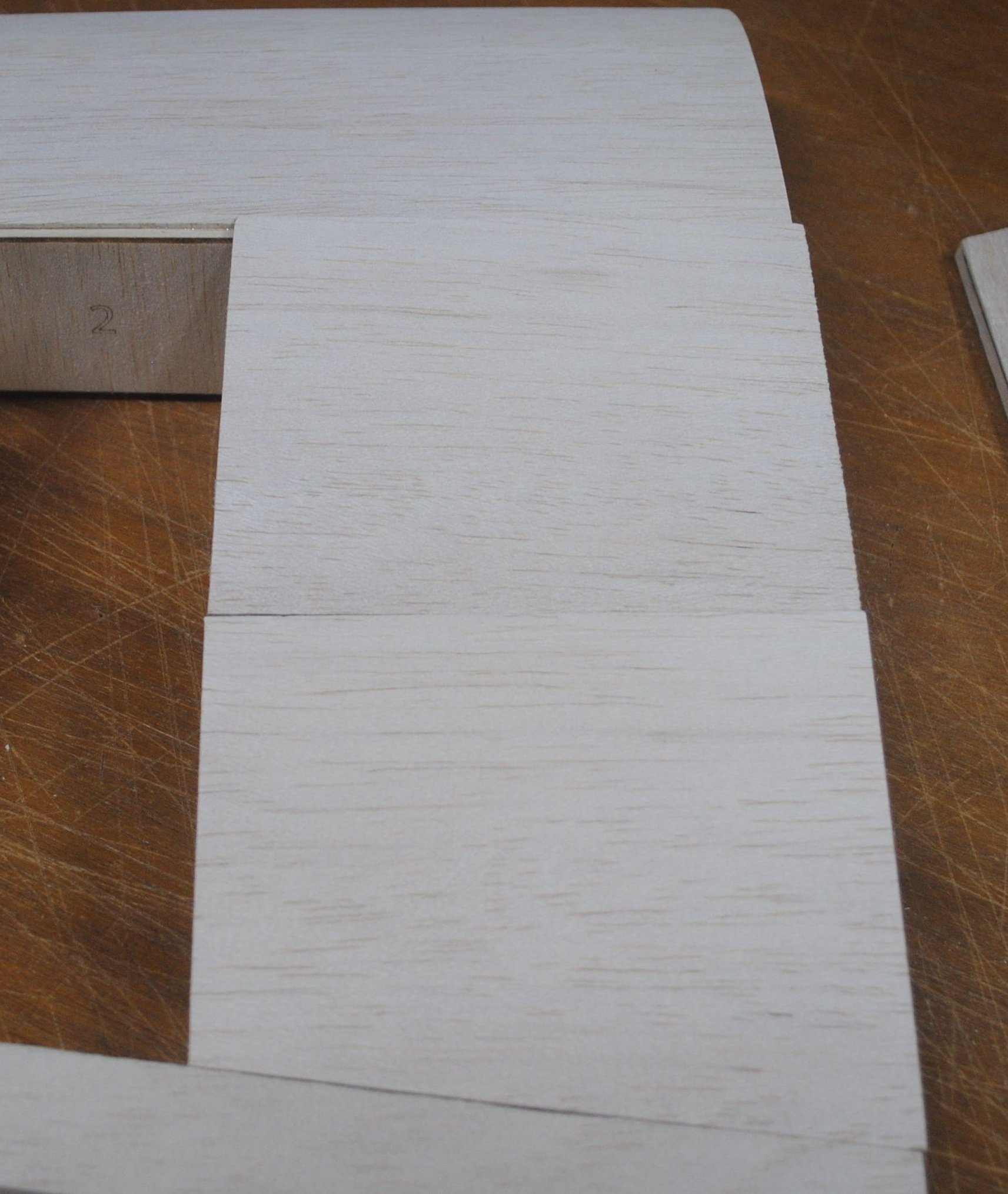
Attach the sheeting at the rear, but not the piece next to the spar. Sand the sheeting and trailing edge assembly flush with the face of the root rib.
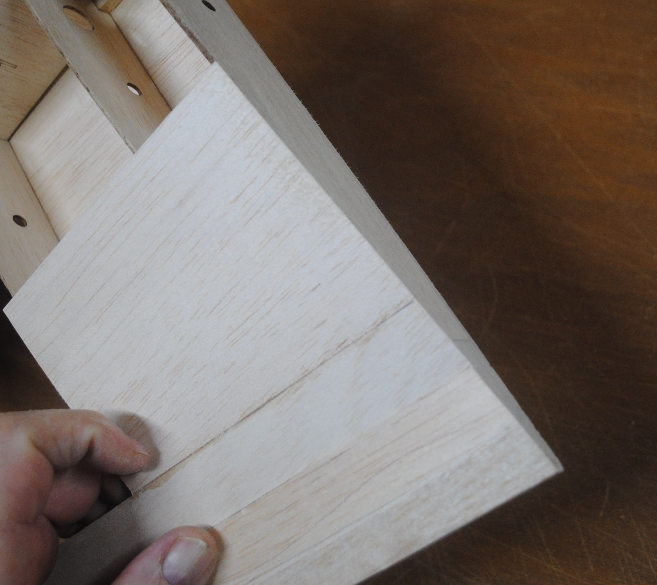
Sand the top of the trailing edge assembly to match the top of the airfoil. The trailing edge should taper down to a thickness of 3/16″. (Why is the trailing edge so thick? A thick trailing edge is able to endure rough handling, and it doesn’t make a difference aerodynamically.)
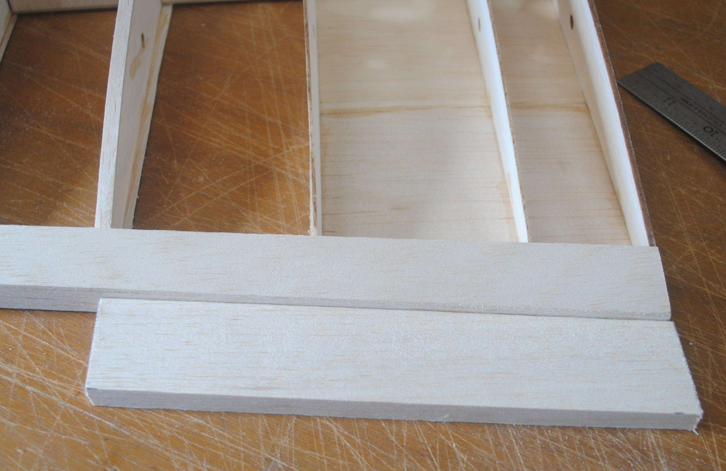
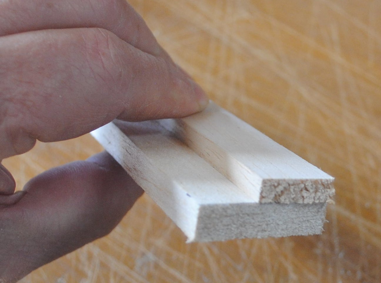
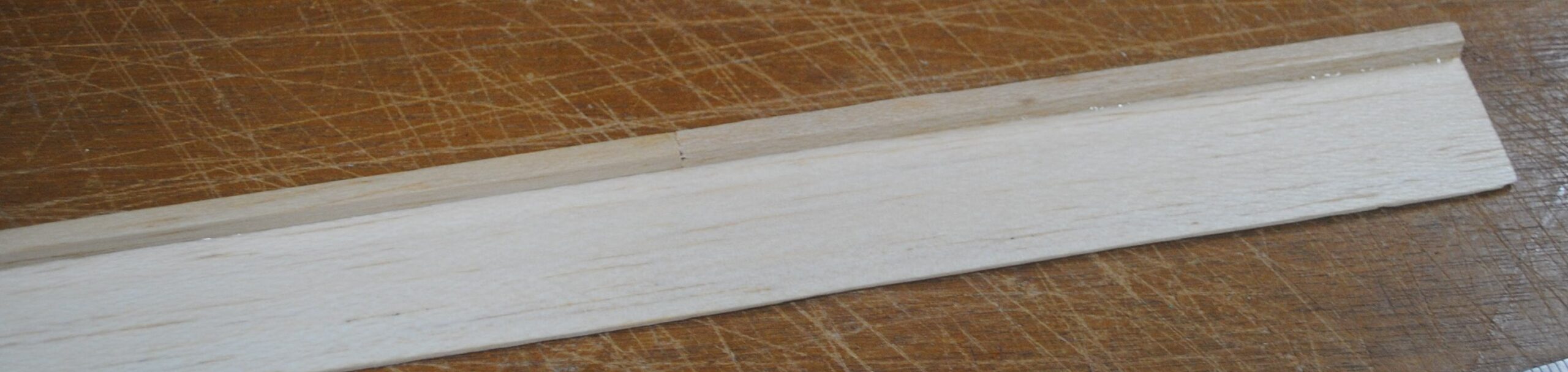
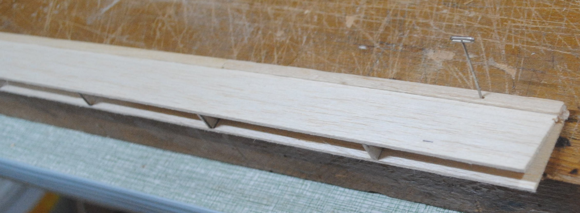
Cut a strip of 1/16″ balsa 1 5/16″ (that’s one and five sixteenths) wide and about 30 inches long. Lay it on the table and glue a 3/16″ x 3/16″ square balsa stick on top of it, flush at one edge.
Add the aileron ribs and the W3 plywood reinforcement for the control horn.
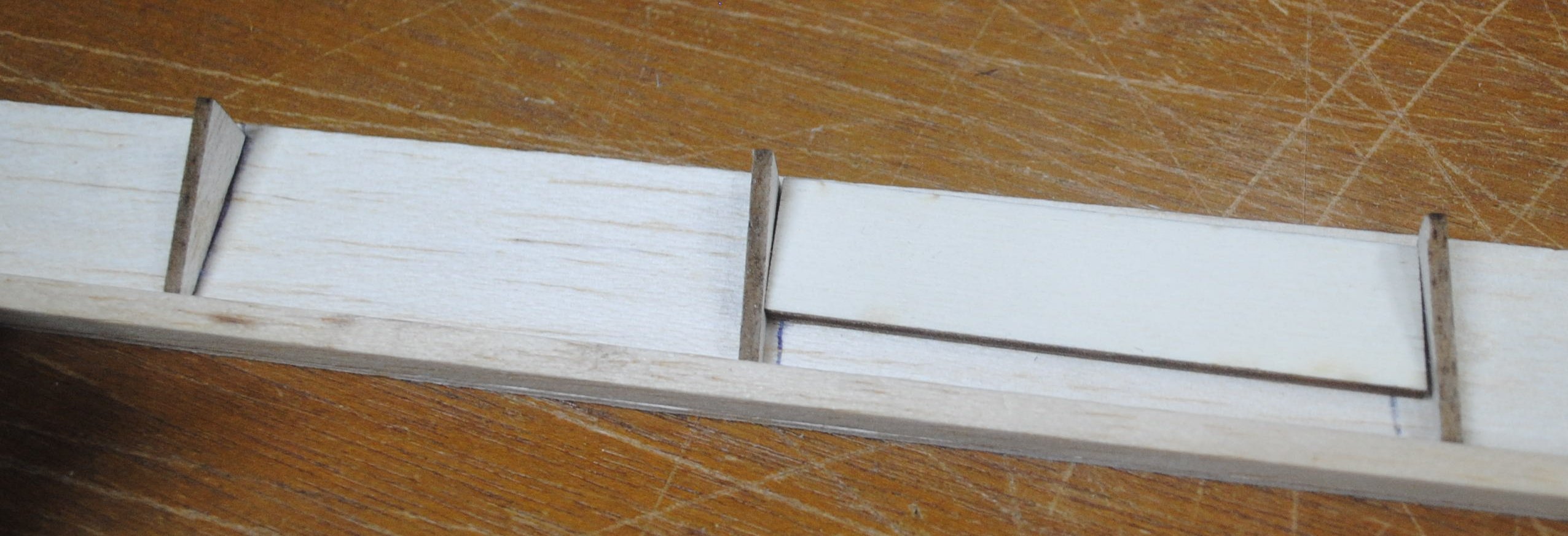
After further consideration I think it’s wise to fill the top of the W3 plywood reinforcement plate with scrap balsa, sanded flush with the top of the two adjacent ribs.
Cut a strip of 1/16″ balsa 1 3/16″ wide (one and three sixteenths) and add it to the top of the aileron. This sheet should be glued to the front of the trailing edge stick and the top of the ribs.
Use a sanding block to sand the sheeting flush with the front of the ribs.
Pin the aileron down with the leading edge protruding over the edge of the table.
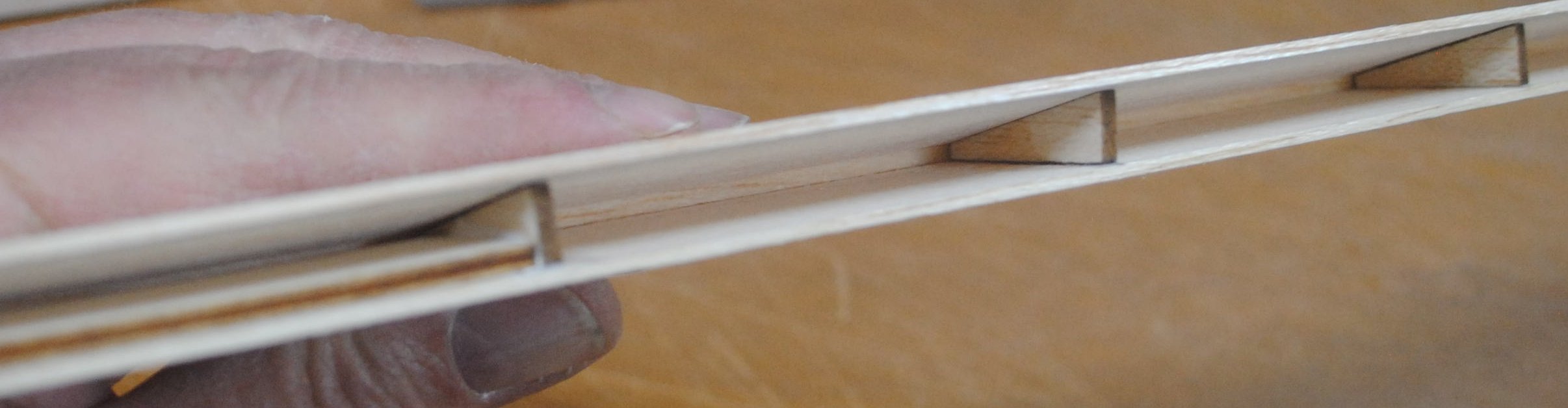
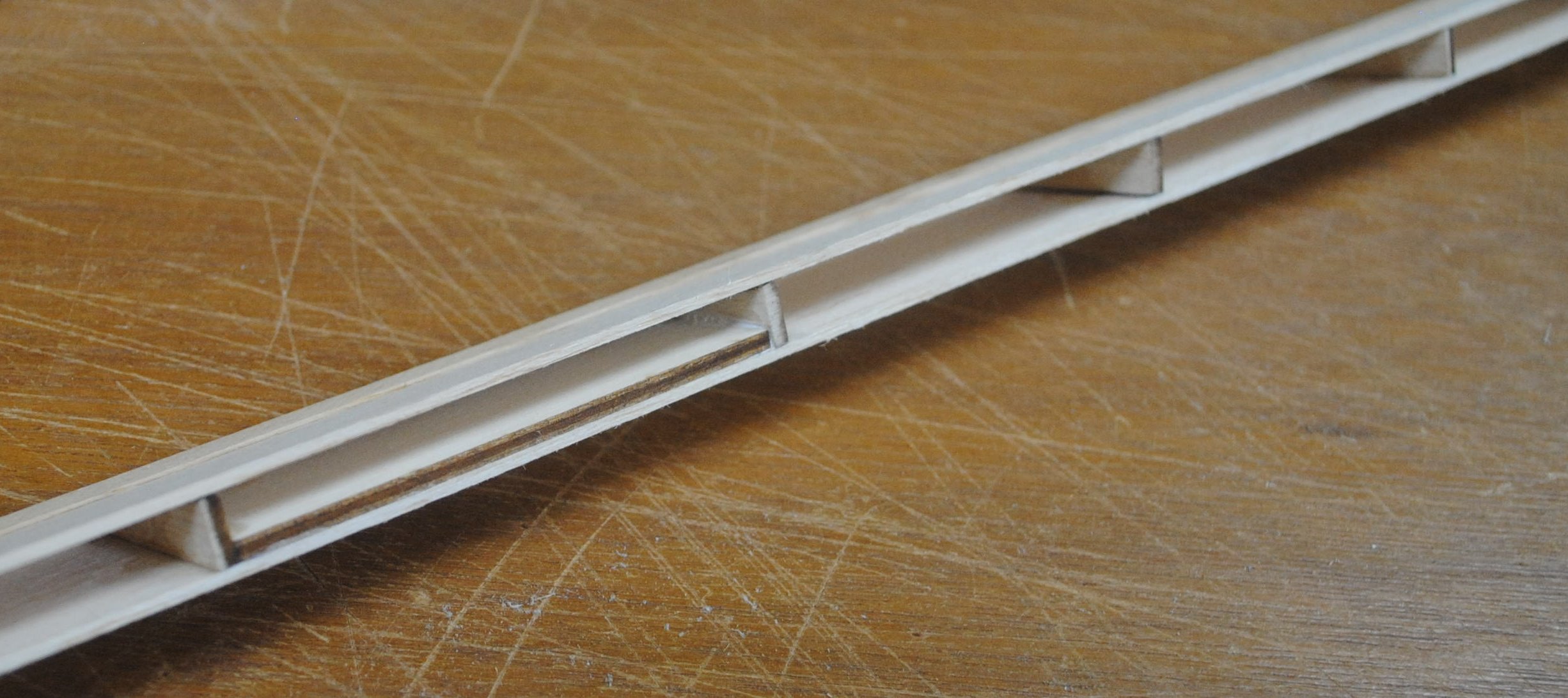
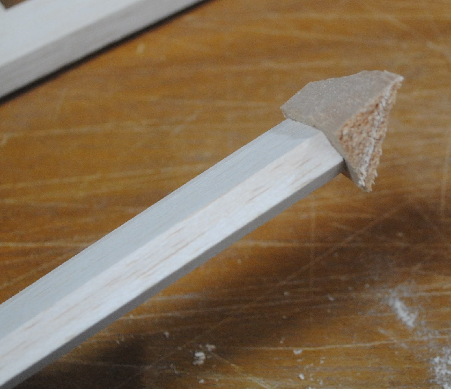
While the aileron is flat, glue a piece of 3/8″ balsa triangle to the aileron with the right angle corner facing forward.

Sand the ends of the aileron. Attach a balsa block to the wingtip end of the aileron.
Sand the top and bottom of the tip block flush with the top and bottom of the aileron. Put the aileron in its place at the trailing edge of the wing. Put a shim between the inboard end and the trailing edge block attached to the wing center section, and pin the aileron and shim. At the outboard end of the aileron use a balsa plank or some other flat object to hold the aileron firmly in place.
Sand the end of the aileron to match the wing tip.
Repeat all of these steps on the opposite wing.
Check the fit to make sure the two wing panels come together properly with the correct dihedral angle, which is 4″ at the tip rib with the other panel flat on the table. If you accidentally sand the root crooked or curved, you can stick a piece of sheet balsa to it and sand it down again. A long sanding block will help your accuracy.
When the wings fit correctly, it’s time to join them.
When everything looks right, cut out the notch in both root ribs behind the spar to allow room for the dihedral brace, and stick the two sides together with glue. The wing root can be glued with medium CA. You can glue the dihedral brace to the spars with medium CA if you think you can slide it together before the glue cures, but I prefer Titebond or epoxy on this joint.
Set your fuselage upside down on a box or other support. Mark the center line on the bottom of the fuselage.
Place the wing in the wing saddle, and line it up with the center line of the fuselage.
Trim the trailing edge to fit in the wing saddle. Leave a little bit of extra space for covering film.
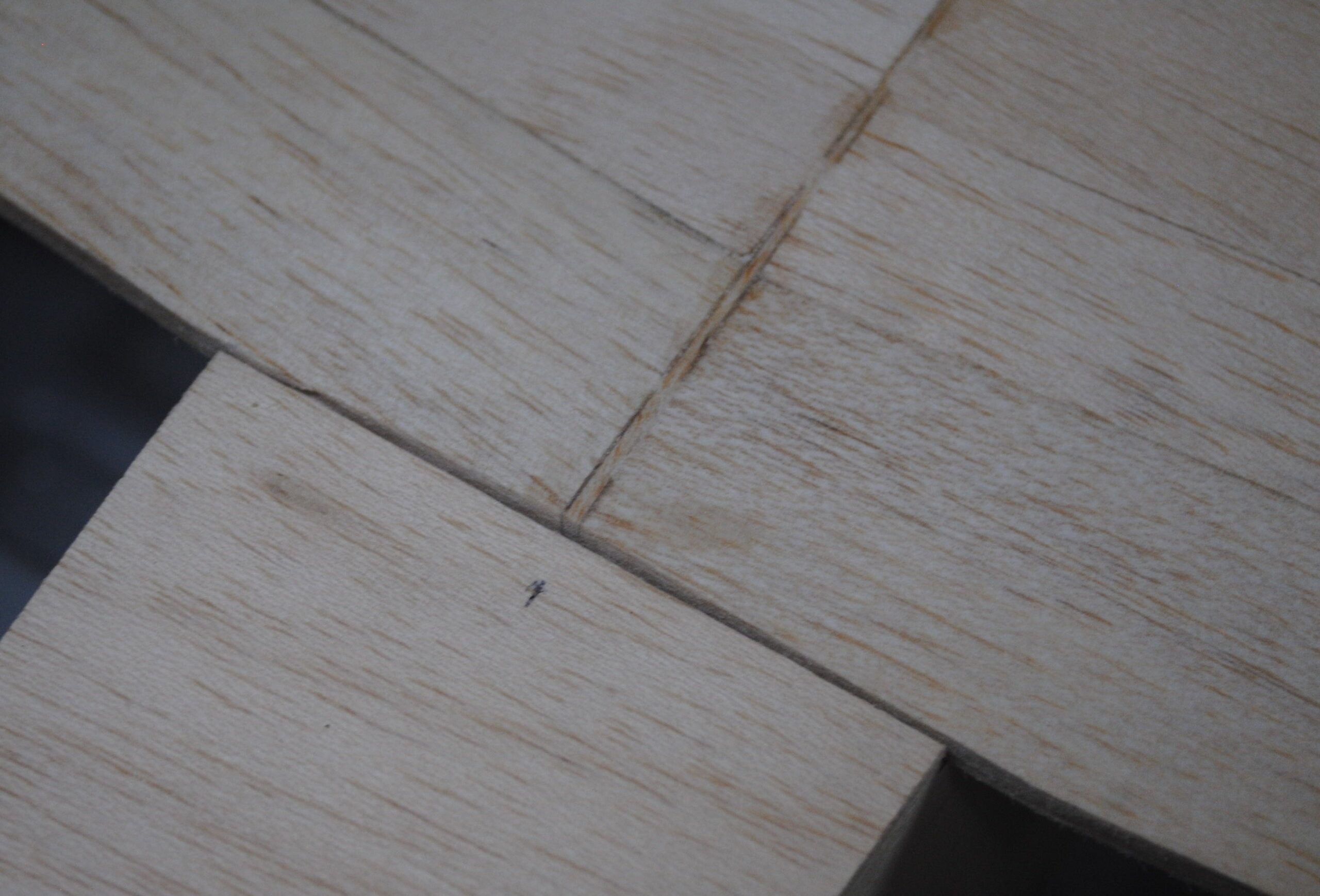
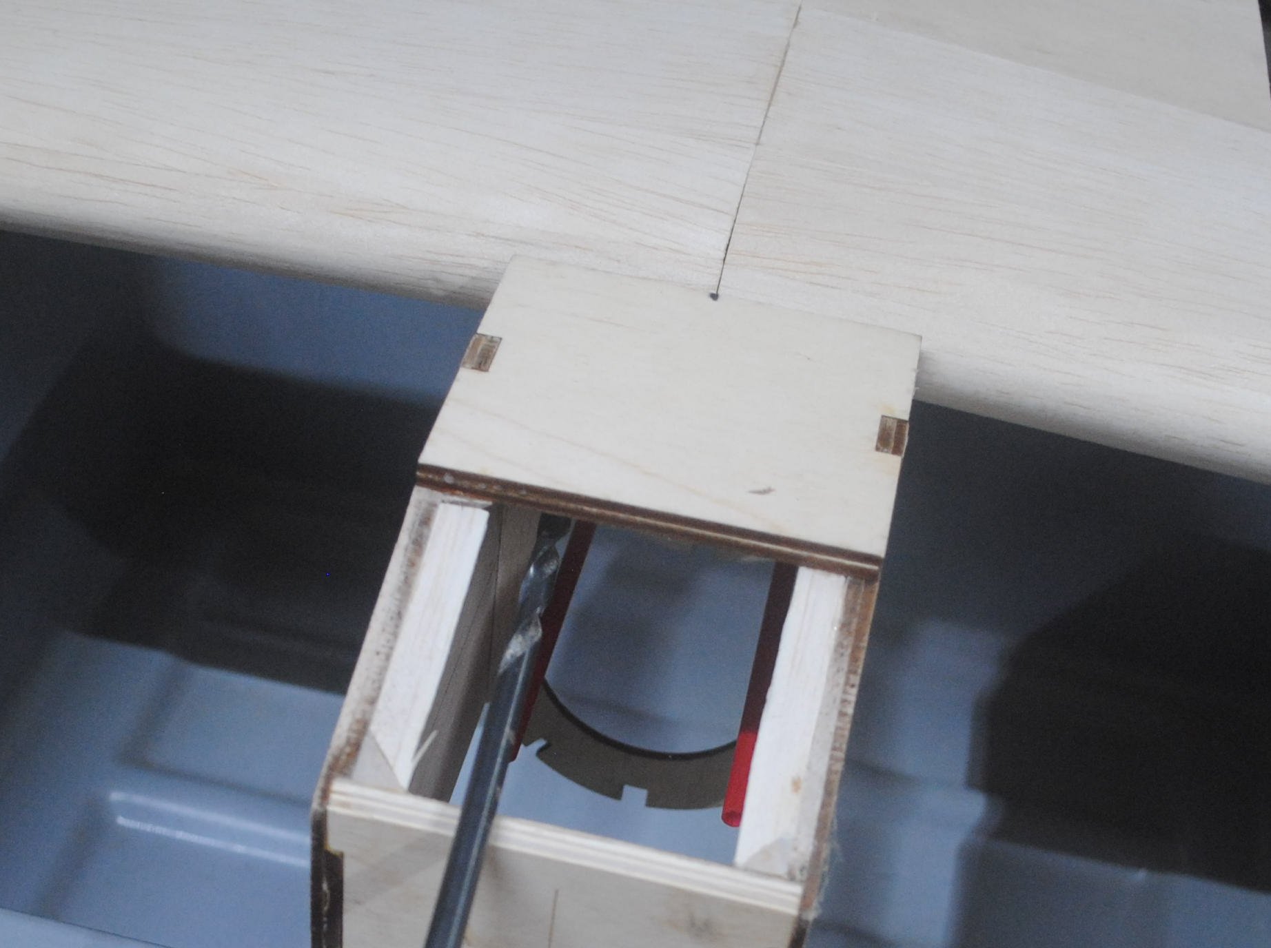
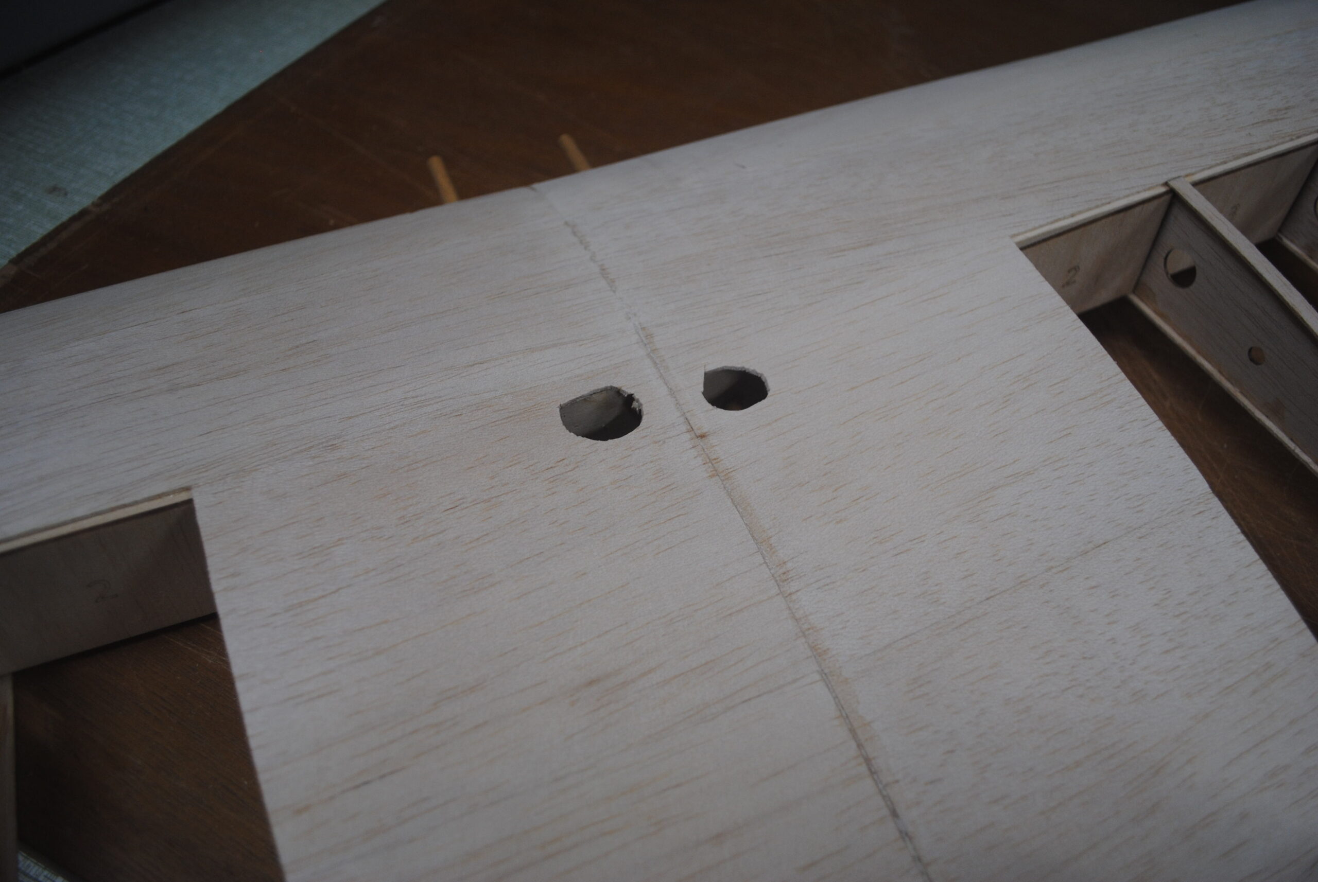
Center the wing and use an extra long 1/4″ drill bit to drill through one of the holes in F3, through the wing leading edge, and all the way through the dihedral brace at the spars. Drill only one hole at this time. Hold the wing firmly so it doesn’t move. It’s probably going to move a little bit. Try to do your best. High drill speed and relatively low pressure are a good idea for soft materials.
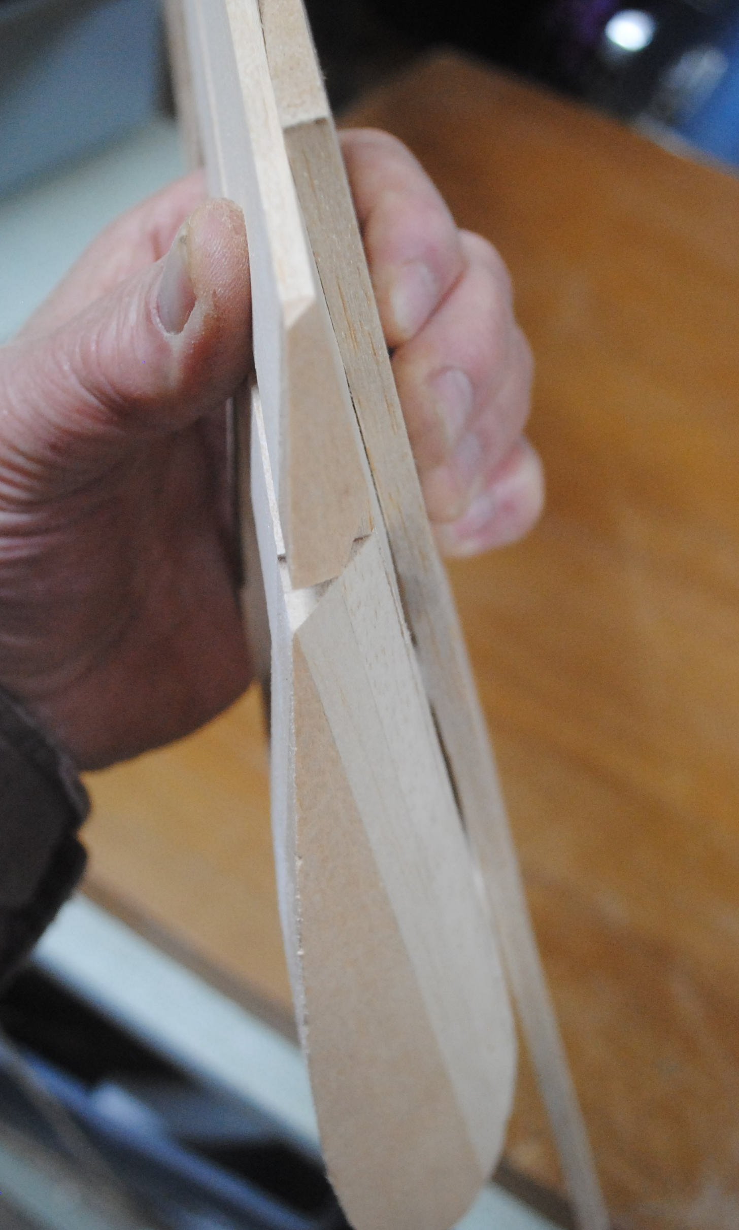
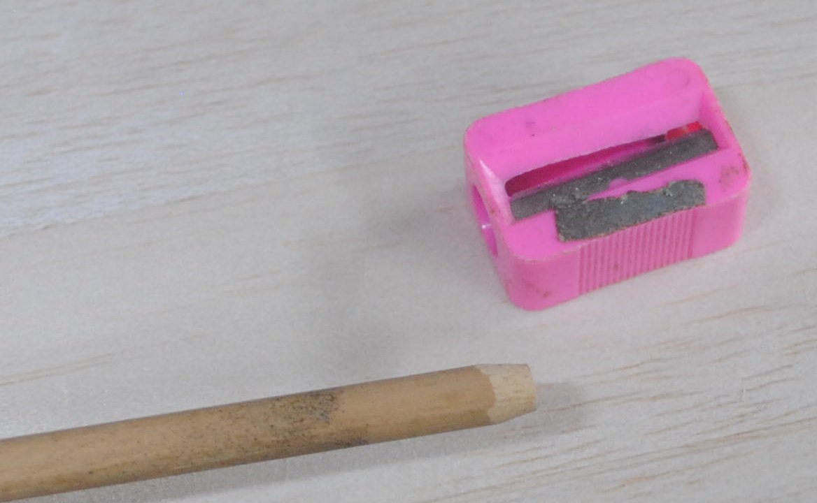
Cut two 1/4″ dowels 6″ long. Use a pencil sharpener to chamfer the ends, or use a sanding block.
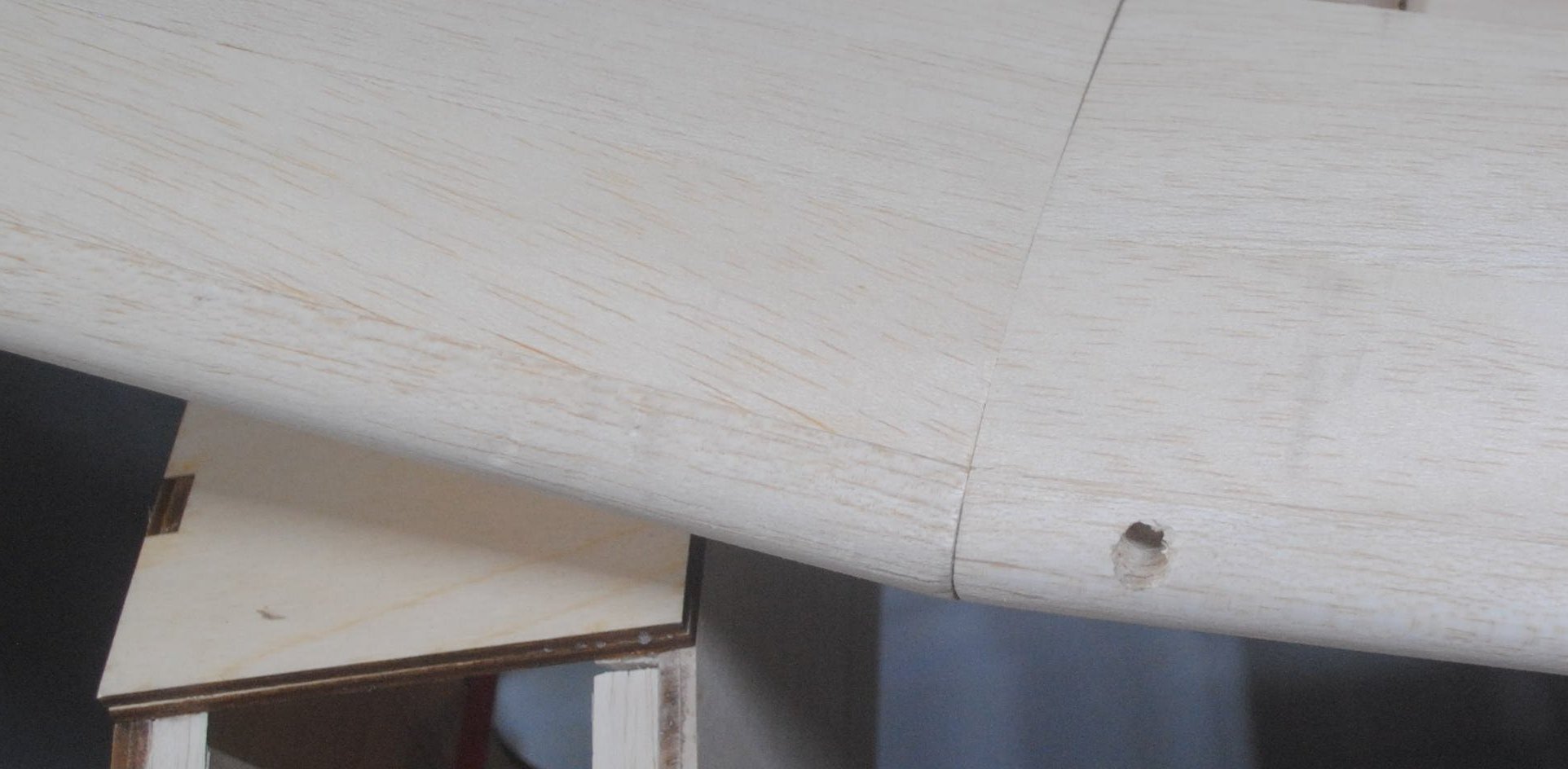
Insert a dowel from the leading edge all the way back to the hole in the dihedral brace. Glue it at the dihedral brace.
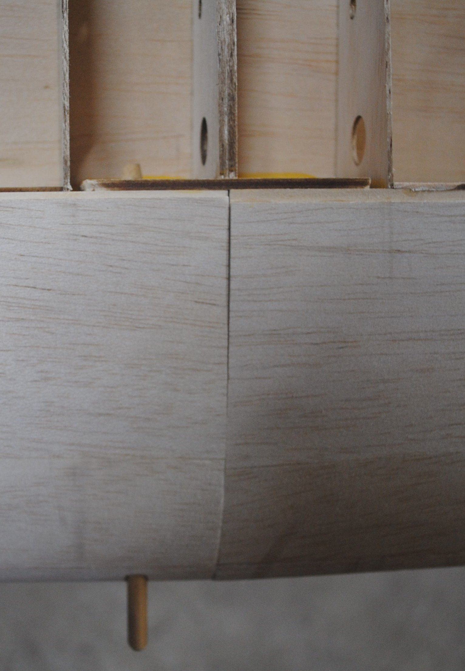
Put the wing back in place in the fuselage, with the dowel through the hole in F3. Drill the second hole and repeat the process with the second dowel. (Do not be tempted to drill both holes at once. If you do, the holes will not line up correctly.)
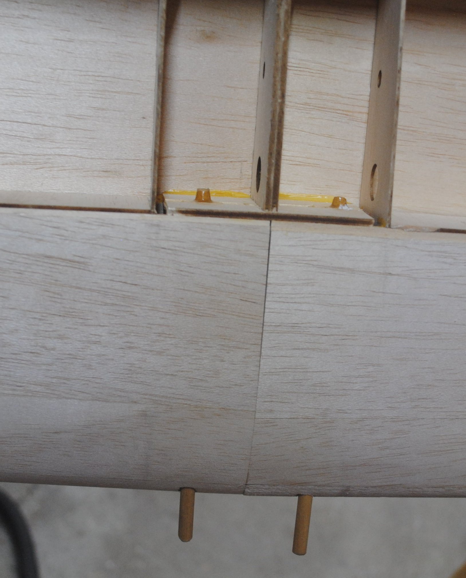
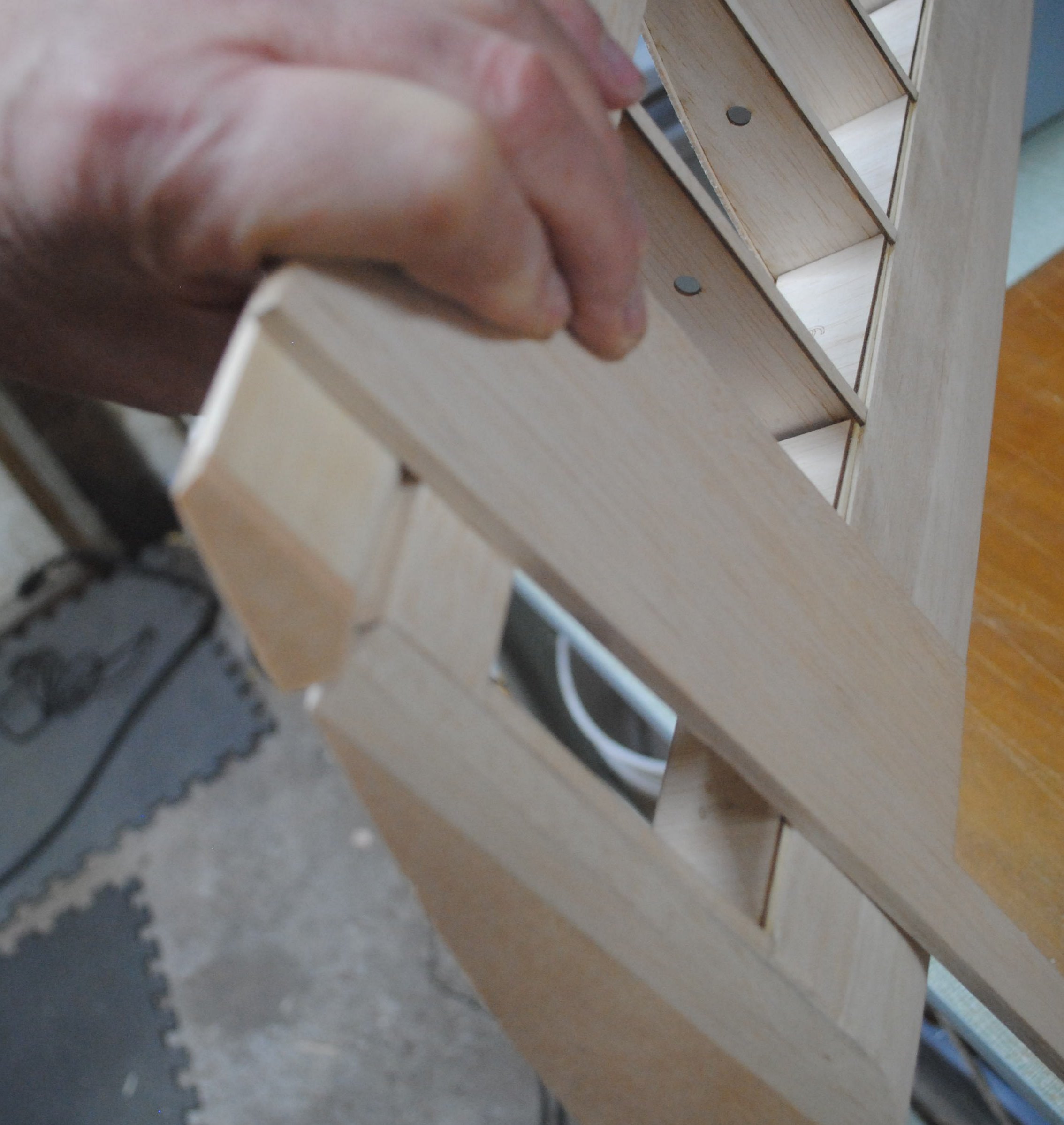
I like the dowel length to be unequal because it makes it easier to put the plane together. You insert the long one, then rotate it until the other one lines up. The dowels in the photo are arguably both too long and could stand to be trimmed a bit.
Attach the last of the top sheeting at the wing center section. Cut holes for servo wire access.
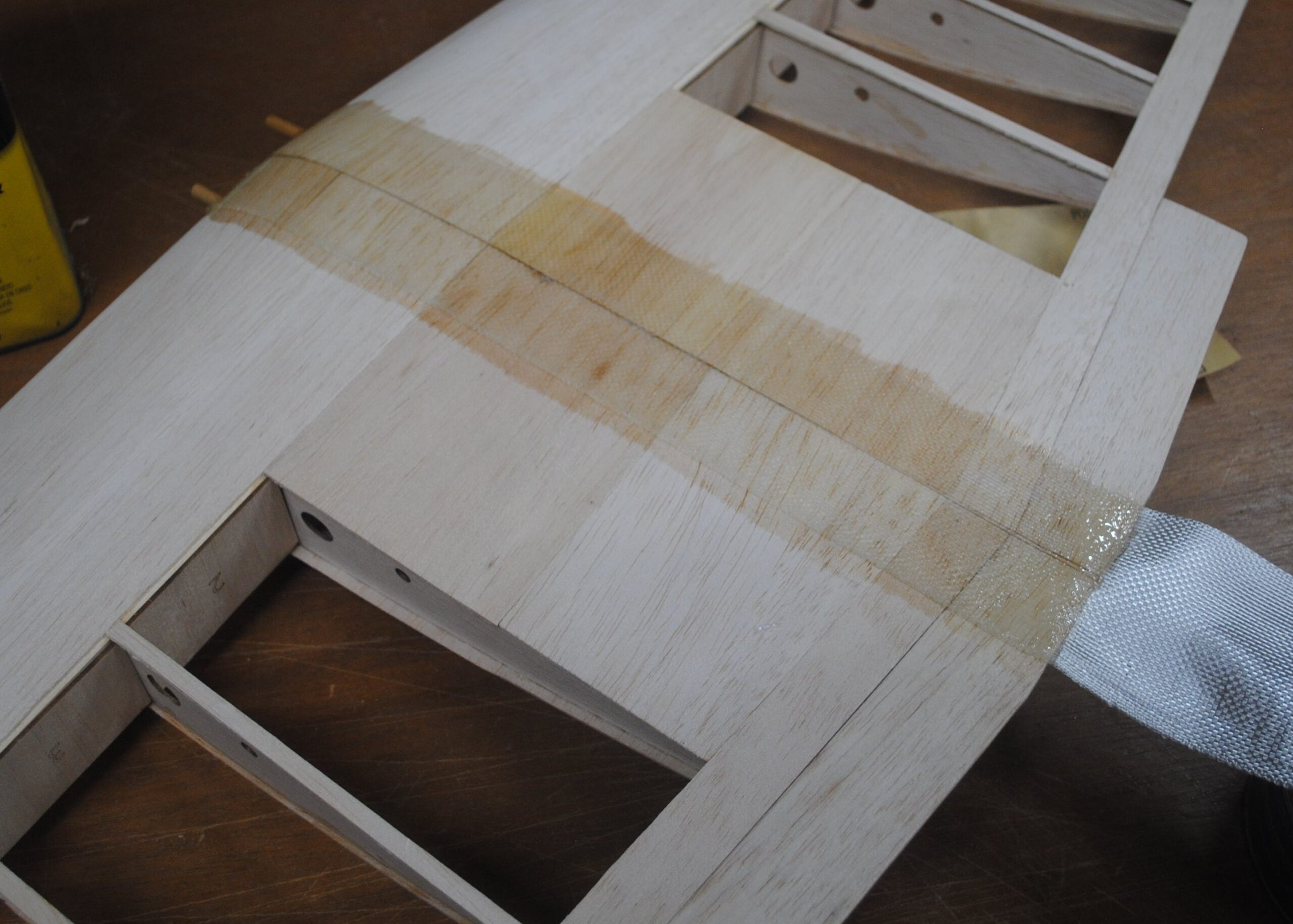
Use resin to attach glass cloth to the center section. The glass cloth supplied in the kit is a bit on the stiff side and has trouble going around corners, so I like to put it on one side first, trim it at the edge, then do the other side the next day.
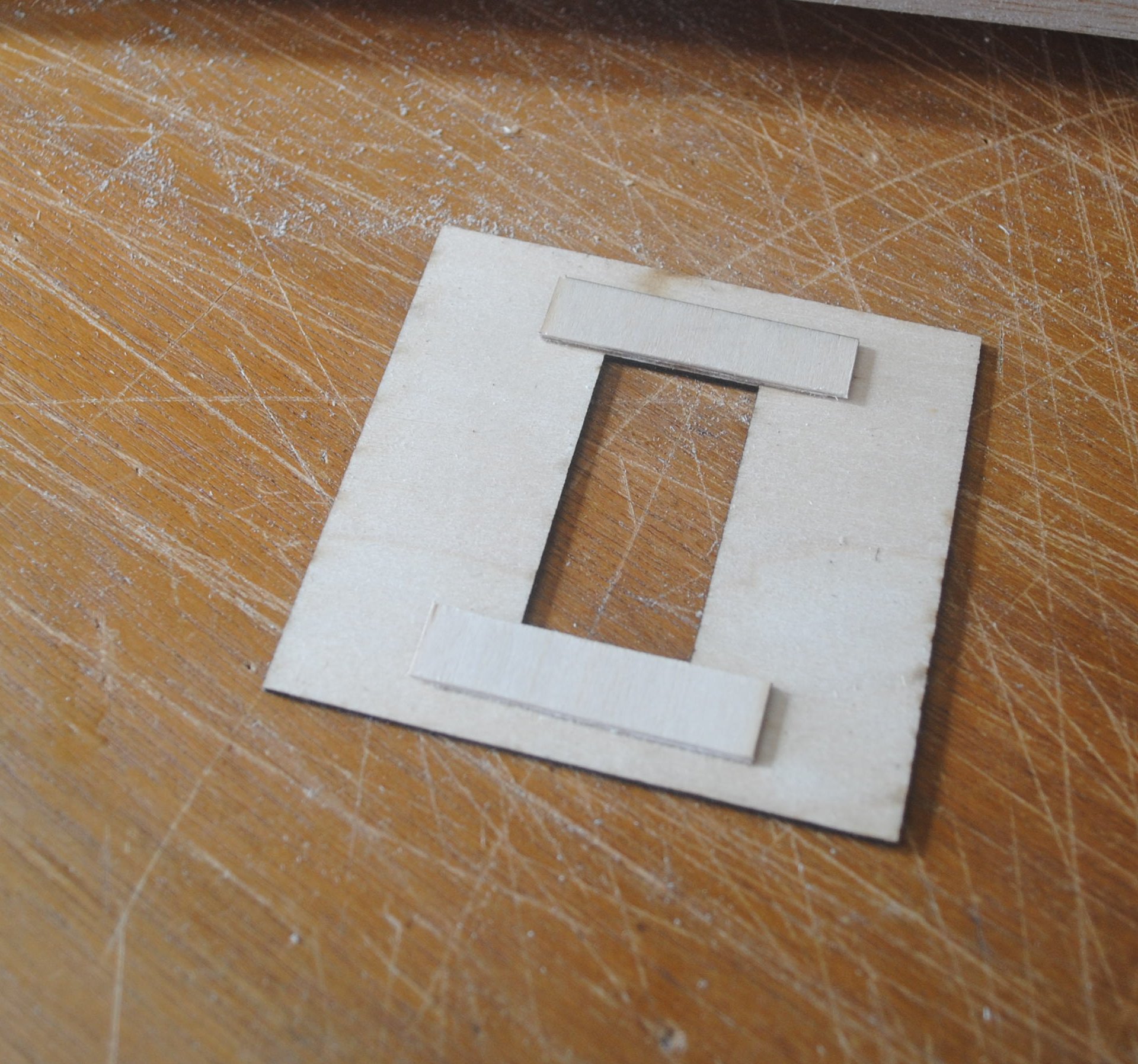
The kit includes a reinforcement plate for the wing retaining bolts.
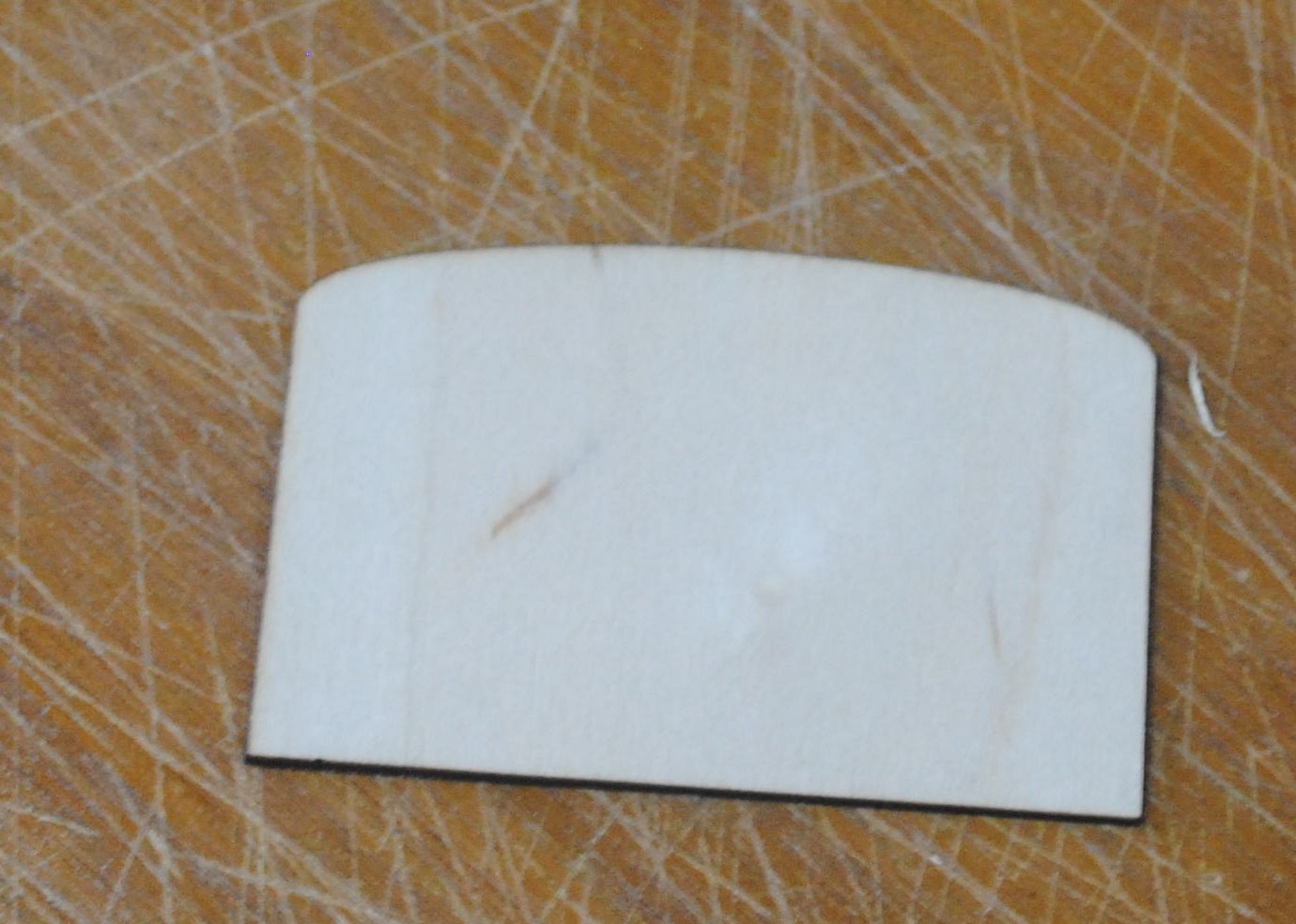
You can glue this plate to the wing now.
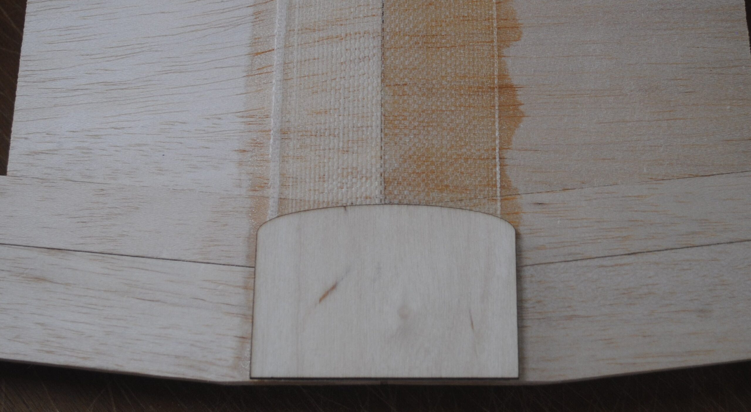
Or you can cover the wing, leaving a little patch at the trailing edge uncovered, and cover the plate, and then glue it onto the wing when it’s time to install the bolts. The advantage of doing it before covering is that you don’t have to worry about the drill bit ripping your covering film. The advantage of doing it later is that it’s easier to cover the wing without the plate in place. So take your pick. If you want to do it now and you need the instructions, you can consult my wing bolt tutorial.
Gently round the sharp edges at the wing tips with fine sand paper, and your wing is ready for covering.