Looking at the Guppy plan again, I noticed that the fuselage parts are made with nothing but straight lines in all the outlines. Although I kind of wanted to build a Guppy, and I think you should as well (with real flaps, not just flaperons), let’s leave that for another day. For the “cutting fuselage parts” project I would rather do a plane with a couple of curves in it. The Sporty Ace biplane by Chuck Cunningham looks like a good prospect.
If you look carefully at the fuselage plan you will see a line labeled SPLICE LINE running the length of the fuselage. Chuck did this so you could use an economical 3 inch wide sheet of wood with a 3/4″ strip edge glued to make it a little bit wider. I measured the fuselage and determined that I would rather use a 4 x 36 inch sheet of balsa because I have these on the shelf for my laser cutting service. You could do it either way you prefer.
As you can see, the top edge of the fuselage sheet is going to be a straight edge. A lot of times the straight edge of a balsa sheet isn’t really straight, so I’m going to check mine with an aluminum ruler.
I know it’s hard to see, but this piece of wood is perfectly straight. Wow! Here’s a photo of what a normal piece of wood looks like with a warped edge. Look at the far edge of the ruler and you’ll see the edge of the wood bulging out in the middle. In this case you would put a straight edge on it and trim the wood to a straight line with a hobby knife, being careful to hold the knife in a vertical position.
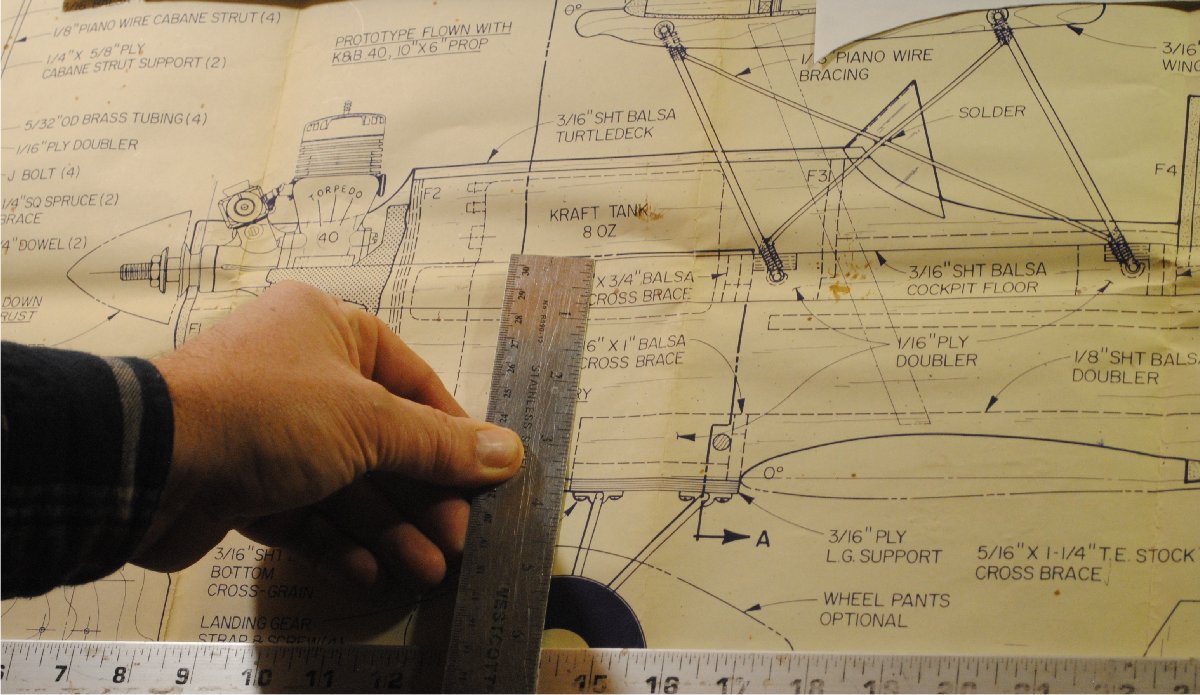
Once you have a nice straight edge on the balsa sheet, it’s time to take a look at the plan. As you can see, the front edge of the fuselage side is perpendicular to the top edge. This is very convenient, because it allows us to use a piece of white office paper for tracing, and we can keep the 90 degree corner. First we need a reference line that extends the front edge, so we can have a mark to measure coordinates from. In the next photo I’m pointing at the reference line.
The tracing paper is placed over the plan, with the top corner lined up with the top corner of the fuselage side in the drawing.
The curved line of the plane’s chin is then traced onto the paper.
The shape is then cut out.
Here’s the template after cutting.
The wing saddle is traced next. The front edge of the paper is placed at the leading edge of the airfoil, the top edge of the paper is lined up with the top edge of the fuselage sheet on the drawing, and then the wing saddle is traced onto the paper.
The fuselage bottom is marked at the edge of the sheet, and the saddle is cut out with scissors. The part corresponding to the rear fuselage bottom is cut with a knife and straight edge.
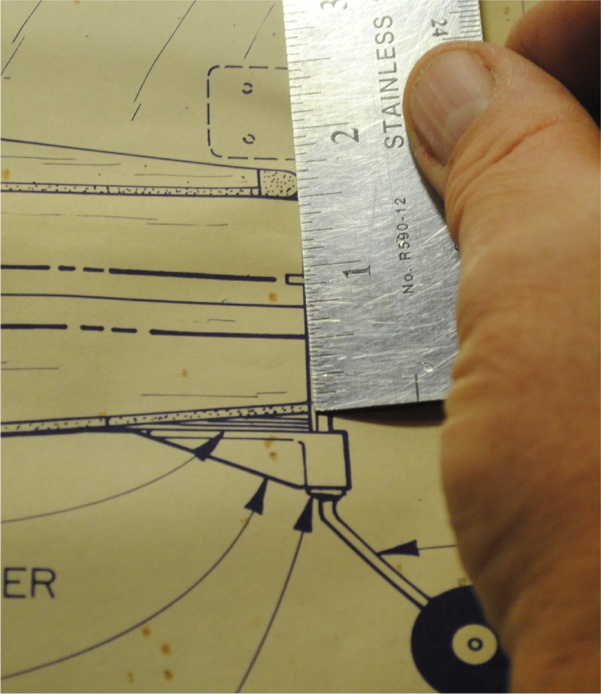
Now it’s time for the fun part. The location of certain coordinates are measured from the plan. I’m interested in the exact locations of the front of the landing gear block and the leading edge of the wing. So I want to measure both of these from the front reference line as well as from the top of the fuselage side. I also want to know the exact height of the nose, so I measure that to make sure I’m drawing the curve in the right place. It looks like the bottom curve starts 1.5″ down.

And the landing gear block is 3.5″ down from the top.
The landing gear block starts 6 7/16″ from the front.
And the leading edge is 8 15/16″ from the reference line.
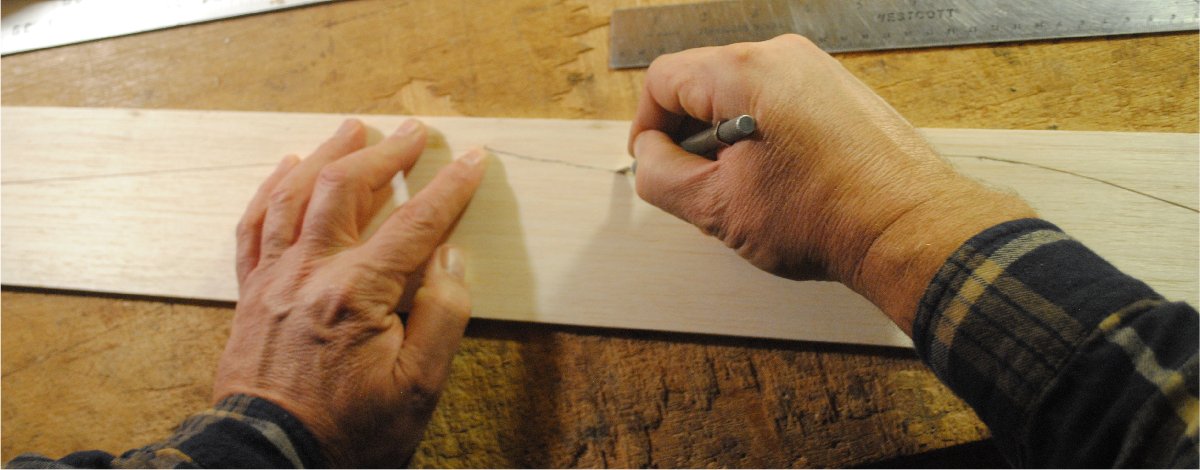
These points are transferred to the balsa sheet and the templates are carefully lined up with the top edge of the wood sheet. Then the curves are drawn onto the wood.
The mark is made where the leading edge of the wing will go.
And the curve is drawn for the wing saddle.
I want to make sure the trailing edge is in exactly the right spot, so I measure it on the plan from the front reference line as well as from the top of the fuselage side.
One careful reader has noticed that some of these steps are redundant. A full sheet of paper is placed at the top edge of the fuselage drawing, and the bottom contours are traced on the paper, with the height of the fuselage built into the template. So why do I bother measuring the height of the nose, and the height at the trailing edge? It’s just to double check myself. The wing incidence is a critical performance factor, so I like to measure twice. If I make a mistake, I’m more likely to catch it by being redundant.
Next I move to the tail end, and with the sheet lined up perfectly with the front edge, I mark the location of the tail post where the sheet will be cut off.
Because this line is vertical on the plan, I can conveniently extend it with a square.
The height of the fuselage sheet at the extreme aft end is measured. It’s 1 7/16″ tall.
The balsa is marked with this measurement.
Now it’s all marked and ready for cutting. I cut the aft fuselage bottom first with a big straight edge.
Then I cut the straight part where the landing gear block goes.
Then I finished by cutting the curved wing saddle and the chin.
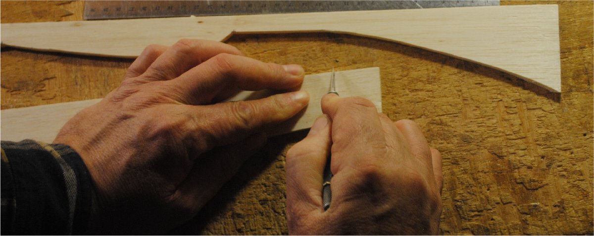
It’s important to hold the knife up straight when cutting. And always try to cut your part a little bit generous so you can do final sanding later to make it exactly right.
Here is the piece after cutting.
Just one other detail. Don’t forget that the tail end was marked to be cut to the correct length.
The part is then compared to the plan.
You can be fairly certain that the straight edges are going to line up accurately, because they are pretty easy. But the curved sections will need to be compared to the plan, sanded carefully, compared again, sanded again, etc, until the part looks just like the picture. Go back to the article on cutting out ribs, and read the part about cutting out the master rib for a complete description of this procedure.
Remember the Guppy fuselage? With nothing but straight lines, it could be measured, marked, and cut out in about five minutes.
One other little detail: If you cut too much off, don’t be afraid to glue on a little strip of wood and take another whack at it.
Once you have the first side cut out accurately, carefully place it on top of the sheet of balsa you’re planning to use for the other side. Use Side 1 as a template to mark Side 2. Use your hobby knife to mark the long straight line along the bottom of the fuselage from the trailing edge to the tail post. The knife gives you a small, accurate mark to use as a guide. Put your straight edge on those cut marks and cut the long straight section off.
Put the two sides back together and use a pen to mark the curved outlines onto Side 2. Set Side 1 aside, and cut the curved lines with your knife, and be a little bit generous with extra wood. Now put the two sides back together. Line them up accurately and pin them with at least half a dozen pins. Carefully trim the second side with a hobby knife to match the first, in the same way as described in the Ribs article.


