The whole plane needs to be sanded to your satisfaction before covering. The bare minimum is shaping the cowl and cockpit sides and rounding all the edges at the bottom of the fuselage.
Cover with your favorite film. Leave the wood bare where the tail meets the fuselage and where the vertical fin meets the horizontal stabilizer. Also leave bare wood where the triangle stock sits on either side of the vertical fin.
If you waited until now to install the nylon wing retaining bolts, mark around the reinforcing plate with a Sharpie.

Cut the film away enough to allow a good glue joint.

Drill and tap the nylon wing bolts as described in my wing bolt tutorial.

With the wing bolted in place, hold the plane with the tail post pointing at your eye. Hold the horizontal stabilizer tightly onto the stabilizer saddle and see if it’s parallel to the wing. If it tilts to one side, gently sand the saddle to make it sit parallel to the wing. Don’t go crazy sanding. A little bit goes a long way.
Attach the horizontal stabilizer to the fuselage with medium CA. You can use whatever glue you want, but it bears mentioning that even when planes crash the tail usually doesn’t come off. Use a square to make sure the vertical fin is straight up when you attach it. Reinforce this joint on either side with 3/8″ triangle stock.

CONTROL SETUP:
The kit includes hardware appropriate for what I consider normal flight. If you’re one of those guys who does everything to the extreme, including excessive engine power, you probably already know how to procure and install extra strength hardware for your flight controls, so have at it. The following instructions are for what could be thought of as a classic or conventional setup.
Hinge the elevators to the stabilizer with two hinges on each side.
Use a sharp hobby knife to cut a notch in the leading edge of the rudder to accommodate the elevator joiner. Try not to bungle up the covering film too much as you make this notch. Hinge the rudder with one hinge at the top, one just above the stabilizer, and one in the fuselage tail post. Don’t glue the hinges in place yet. Take this opportunity to check for interference between the rudder and elevator. Keep trimming the notch until you achieve full motion without interference. The notch will probably get bigger than you expect.
When the notch is big enough, fuel proof the exposed wood. I find that thin CA works well, or you could use dope or epoxy.
Install the aileron servos and linkage. The aileron horns are held in place with #2 sheet metal screws, without a nylon backing plate. 1/16″ holes are drilled into the bottom of the aileron, through the 1/8″ plywood screw plate. Be very careful not to drill all the way through the top of the aileron. The holes should be in the bottom only. Harden the holes with thin CA.

This design is adequate for what I would consider normal performance, but if you’re a maniac pilot you may want to laminate a piece of 1/16″ ply to the bottom of the aileron for extra strength. Make it long enough to span across the aileron rib on either side of the control horn. Cover it with matching film and laminate it to bare wood on the bottom of the aileron. Then attach the horn with screws as described above.
Install the tail wheel assembly according to the manufacturer’s instructions, or you can use your favorite method. My favorite method is detailed on the plan for your consideration. The strap is cut from a fuel jug.

I use a piece of fuel line as a cushion on the tiller arm and bend the end of the wire down slightly to prevent the tubing from slipping off. The strap is held in place while a 1/16″ hole is drilled all the way through. (Don’t drill into your finger.) The hole is enlarged to 3/32″ on one side of the strap, and the strap is retained by a 2-56 screw through the big hole, through the hole in the rudder, and then into the smaller hole on the other side where the screw cuts its own threads.

Use the long threaded metal rods supplied in the kit to reinforce the Dubro push rods where they exit the fuselage at the tail. Insert the unthreaded end into the inner nylon tube. If it has a burr from being cut at the factory, it will not go in smoothly. The burr can be sanded off with a sanding block or a file. Insert the rod all the way up to the thread, then screw about 1/4″ of the thread into the nylon tube.

The following photo shows how long the rod is, inside the push rod tube. This reinforcement will prevent bending under flight loads.

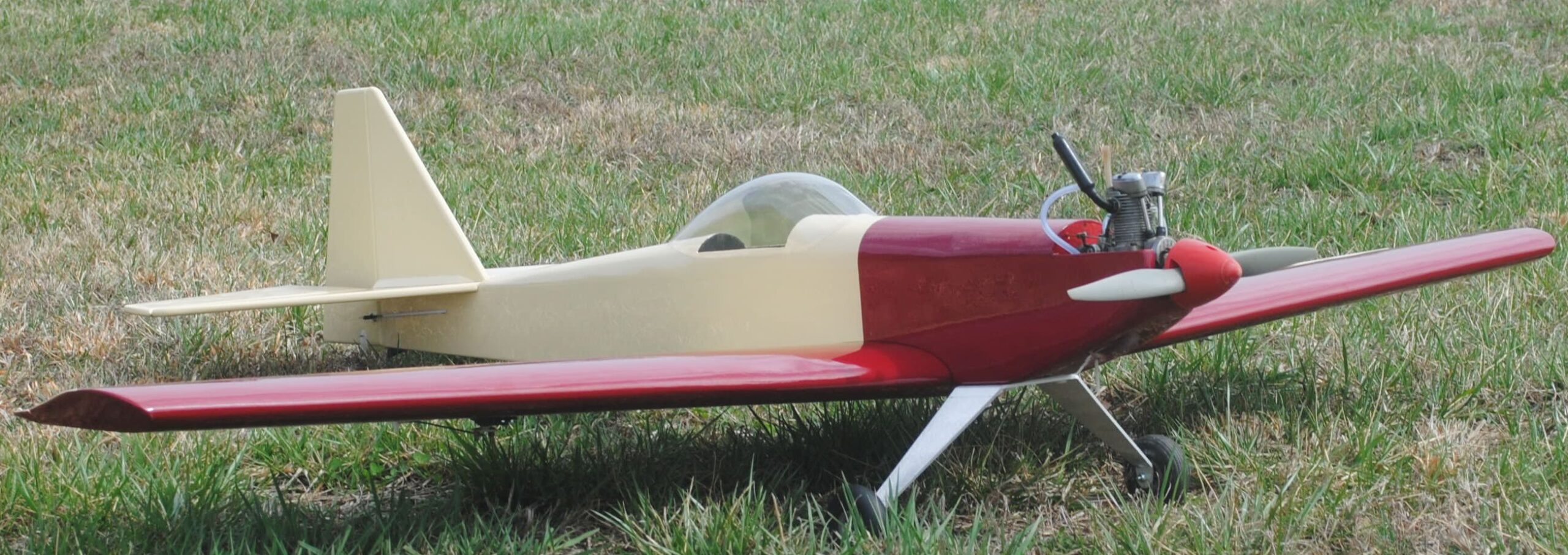
Install the throttle cable housing where it belongs. Fuel proof the engine compartment if necessary with dope or epoxy. Install the fuel tank and engine, or the battery and motor. Install the propeller and spinner.
The following sequence is illustrated with photos from another kit, but it’s the same thing.
Landing gear axles are made from 8-32 bolts and ny-lock nuts. Insert the bolts in the wheels. If the bolt doesn’t fit through the wheel hub or if the wheel binds, you’ll have to enlarge the hole slightly to allow the wheel to spin freely. Sometimes it’s best to use a drill bit that’s not really big enough, and wobble it a little bit to munch the plastic slightly, rather than use an oversize bit. The first nut goes on after the wheel.
Use a crescent wrench to twist the axle mounting area of the landing gear to provide about 2 degrees of toe-in per side.

Put the end of the bolt through the hole in the landing gear, and hold it in place with the second nut. Use a thin wrench or long nose vise grips to hold the first nut while you tighten the second nut against the landing gear.

Attach the landing gear to the plane. If you have a heavy pilot (why?) install it now because it will be slightly behind the center of gravity.
When all the immovable stuff is in place, assemble the plane and check the center of gravity, which is supposed to be at the rear edge of the spar. Install the servos and switch in the tray if you want to use it. Adjust the position of the receiver, servos and possibly a receiver battery or speed control to achieve the correct center of gravity. Install everything once you figure out where it’s supposed to go.
For the prototype, the battery went in the same place as the servos. A long strip of foam went into the space first.

Then the battery.
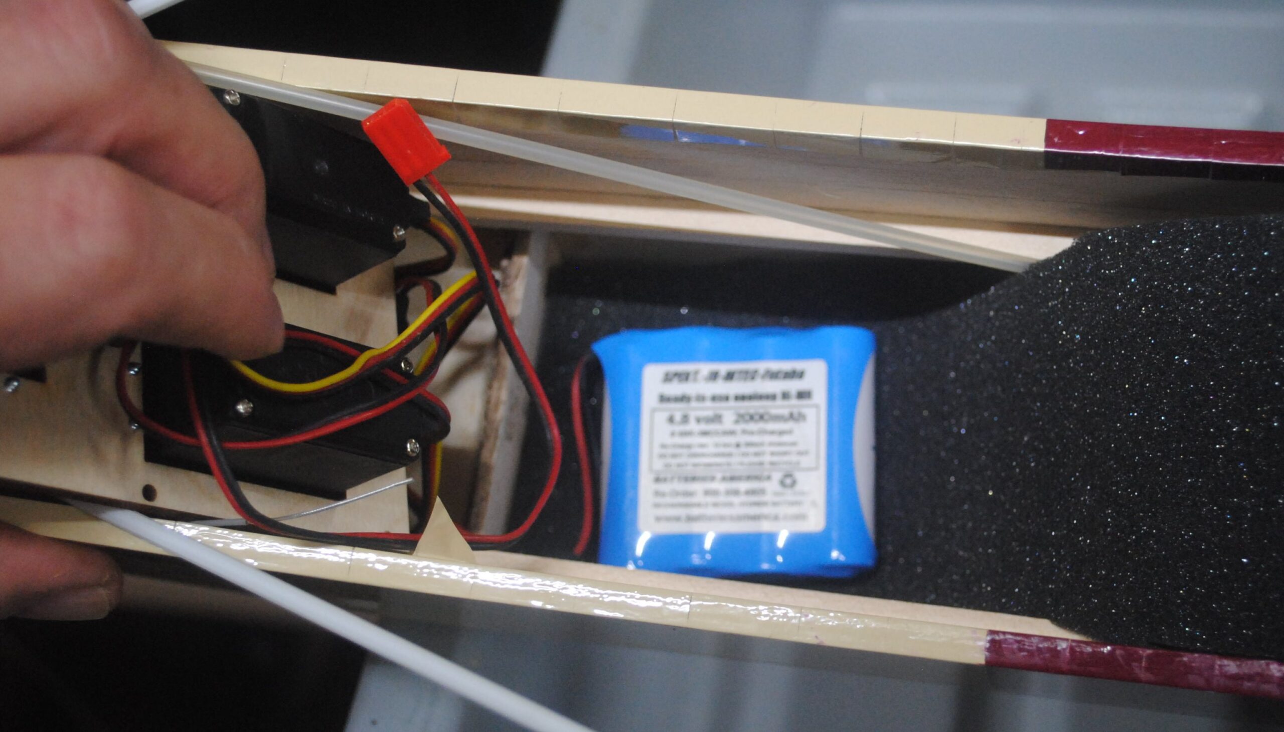
Then the foam was folded over and trimmed.

Then the servo tray was screwed in place over it so the servos would hold the foam.

Push rods are held by little brackets included in the kit. The receiver is cushioned and held by a plate attached with screws to the servo rails. Long metal rods are used on the front end of the push rod tubes to prevent flexing. In this case the threaded end is screwed into the tube, approximately even with F6, and the smooth end protrudes all the way to the servo.

A balsa block braces the throttle cable housing, which is attached with another plywood bracket.

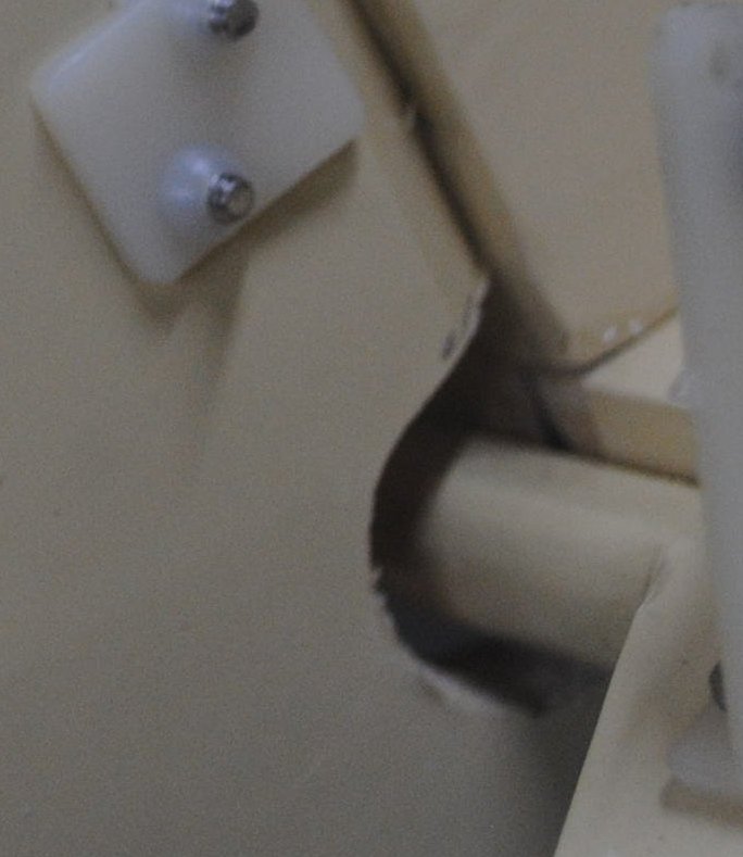
The head of the switch has a hole drilled crosswise. It’s controlled by a 1/16″ wire with an L bend that goes through the hole. The other end of the wire goes through a hole in the side of the fuselage so it can be turned on and off from outside.
The canopy is extensively trimmed to fit the top of the fuselage. Don’t forget to remove the protective film from the canopy. The 1/16″ music wire handle for the on/off switch can also be seen in this view.
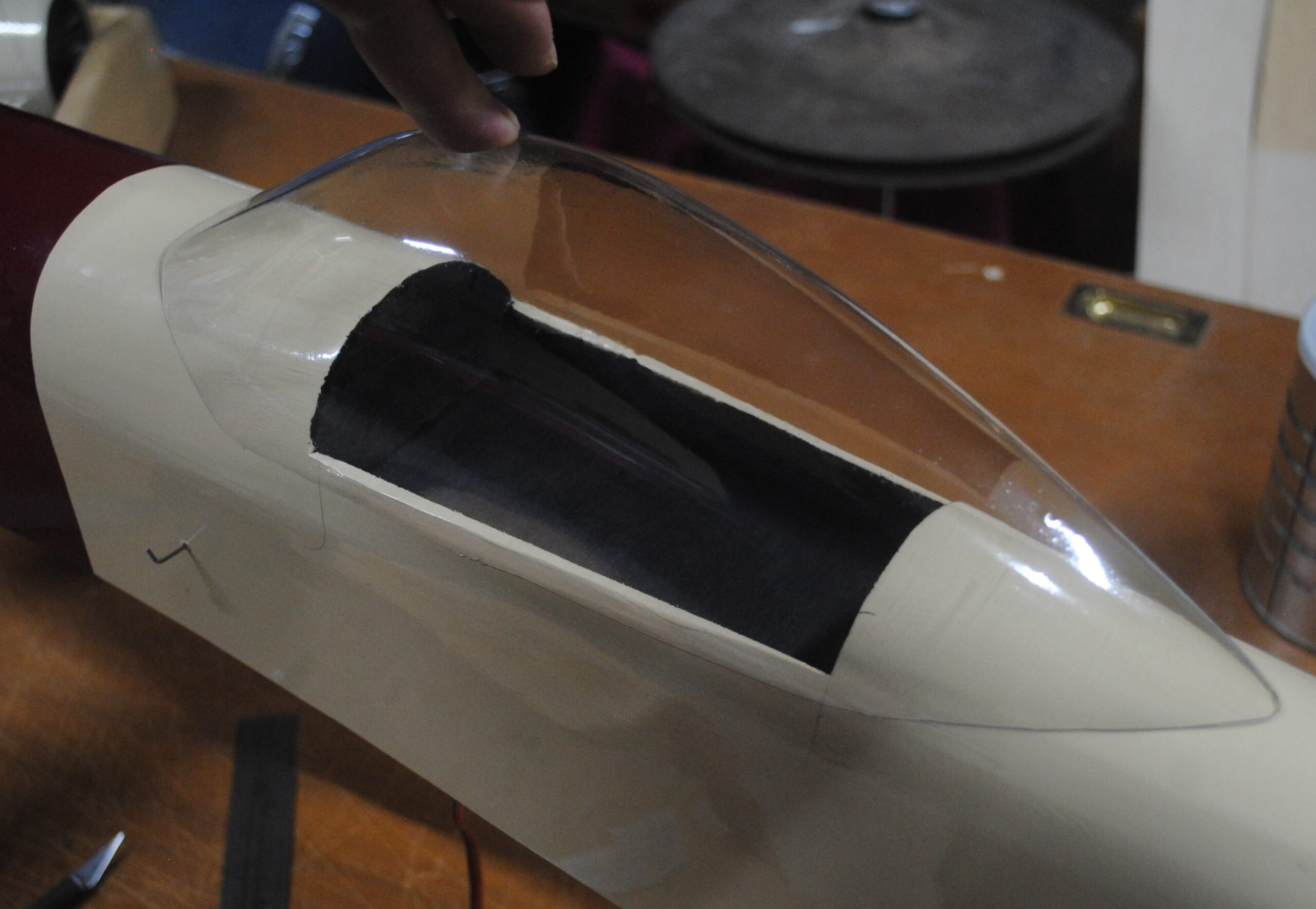
The canopy is attached with E-6000 or an equivalent clone from Gorilla or other company. It’s held with tape while the glue cures overnight. Scrap balsa sticks can be taped on to hold the canopy tight against the cockpit sides.

Recommended control throws:
Ailerons 1/2″ up, 3/8″ down
Elevator 1″ to 1.25″ up and down
Rudder 1.5″ right and left, or however much you want.
Try not to crash.